Build Your Own Clone Message Board

It is currently Sun Apr 28, 2024 1:14 am

All times are UTC - 6 hours


Post new topic Reply to topic  [ 10 posts ] 
Author Message
PostPosted: Tue Mar 28, 2023 3:47 pm 
Offline

Joined: Wed Aug 10, 2022 11:17 pm
Posts: 28
I designed the enclosure for my Green Pony to use one of those fancy 3PDT switches with the LED ring at the bottom instead of the on board LED.

I grabbed a guitar PCB 3PDT breakout board with the required wiring for the LED switch, (which the data sheet says includes a CLR for the LEDs (there are half a dozen on each switch)). I would like to make sure I hook everything up to the right places. The GuitarPCB board has pads for Board In, Board Out, Tip In, Tip Out, several pads for ground and 9V supply.

Looking at the Green Pony board there is an In/Out in the top corners, which seem to correspond to pad numbers 4 & 8 in the switch notch, but I suspect I could just wire directly to the IN/OUT pads.

It looks to me like Pad 2 in the switch notch is 9V+, but I’m at a loss for where ground is.

All of this said, I could just run hookup wire directly to the V+, V-, IN, and OUT pads at the top of the board, but I’m not sure that won’t cook something important.

Did I bite off more than I could chew? It’s starting to look that way, help would be appreciated.


Top
 Profile  
 
PostPosted: Tue Mar 28, 2023 8:05 pm 
Offline
Moderator
User avatar

Joined: Tue Jan 02, 2007 1:24 pm
Posts: 16224
Location: Albany, NY
Could ya post a pic of the 3PDT board you're using so we can see what you're looking at?

_________________
“My favorite programming language is SOLDER” - Bob Pease (RIP)

My Website * My Musical Gear * My DIY Pedals: Pg.1 - Pg.2


Top
 Profile  
 
PostPosted: Wed Mar 29, 2023 7:34 am 
Offline

Joined: Wed Aug 10, 2022 11:17 pm
Posts: 28
This is something, if I had half a brain I would have done with the original post, thanks for reminding me.

Gotta love technology, I was able to resize the gigantic original file


Attachments:
E35A2380-07B4-43A8-8A2A-FABE7C8076E3.jpeg
E35A2380-07B4-43A8-8A2A-FABE7C8076E3.jpeg [ 65.77 KiB | Viewed 1080 times ]
Top
 Profile  
 
PostPosted: Wed Mar 29, 2023 10:06 am 
Offline
Moderator
User avatar

Joined: Tue Jan 02, 2007 1:24 pm
Posts: 16224
Location: Albany, NY
OK, the image below shows how I'd wire it up. The I/O and DC jacks should be wired to the top of the main PCB per the Green Pony's instructions. Rather than running a wire all the way from the DC jack to one of the +9V eyelets on the 3PDT board, I'd use the top lead of the 1N4001 diode at the lower left of the main PCB for the power connection (red wire on my diagram).

Two options on the LED installation:

  • If you're using the LED installation on the 3PDT mini-board, leave out the wire shown in green and install the CLR and LED on the mini-board per the GuitarPCB instructions.
  • If you use the LED installation on the BYOC main PCB, then leave out the CLR and LED on the mini-board and run that green wire from the left-most D1 eyelet to eyelet 1 on the main board.

Attachment:
3PDT_miniPCB_hookup.jpg
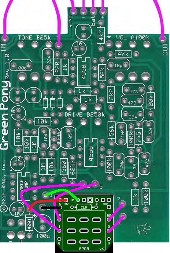
3PDT_miniPCB_hookup.jpg [ 120.97 KiB | Viewed 1073 times ]

_________________
“My favorite programming language is SOLDER” - Bob Pease (RIP)

My Website * My Musical Gear * My DIY Pedals: Pg.1 - Pg.2


Top
 Profile  
 
PostPosted: Wed Mar 29, 2023 1:51 pm 
Offline

Joined: Wed Aug 10, 2022 11:17 pm
Posts: 28
Here is a link to the LED switch https://guitarpedalparts.com/collections/led-switches-1/products/3pdt-foot-switch-with-led-ring-red I have

I was hoping the breakout board would make it easier, but maybe there is a better way? There is a a big difference, in that instead of solid leads, the switch I have in hand has hook up wire


Top
 Profile  
 
PostPosted: Wed Mar 29, 2023 3:16 pm 
Offline
Moderator
User avatar

Joined: Tue Jan 02, 2007 1:24 pm
Posts: 16224
Location: Albany, NY
Does your switch have two wires for the LEDs or three?

_________________
“My favorite programming language is SOLDER” - Bob Pease (RIP)

My Website * My Musical Gear * My DIY Pedals: Pg.1 - Pg.2


Top
 Profile  
 
PostPosted: Wed Mar 29, 2023 8:35 pm 
Offline

Joined: Wed Aug 10, 2022 11:17 pm
Posts: 28
Just two


Top
 Profile  
 
PostPosted: Wed Mar 29, 2023 9:10 pm 
Offline
Moderator
User avatar

Joined: Tue Jan 02, 2007 1:24 pm
Posts: 16224
Location: Albany, NY
OK, then you'll leave out the green wire in my diagram, and solder the colored LED wire to the center D1 eyelet (with the square solder pad) and the black LED wire to the left D1 eyelet. Same hookup as the LED in the GuitarPCB diagram below, except you'll be using the wires rather than the LED leads. Unless the switch came with a specific recommendation for the resistance value of the CLR, I'd go with a 1 Kohm since you're lighting 6 LEDs in that switch.

Attachment:
GPCB_LED_connection.jpg
GPCB_LED_connection.jpg [ 34.47 KiB | Viewed 1040 times ]

_________________
“My favorite programming language is SOLDER” - Bob Pease (RIP)

My Website * My Musical Gear * My DIY Pedals: Pg.1 - Pg.2


Top
 Profile  
 
PostPosted: Wed Mar 29, 2023 10:20 pm 
Offline

Joined: Wed Aug 10, 2022 11:17 pm
Posts: 28
According to the data sheet there is a CLR built into it. I think they are 1mm LEDs, but I appreciate the suggestion.


Top
 Profile  
 
PostPosted: Thu Mar 30, 2023 12:25 pm 
Offline
Moderator
User avatar

Joined: Tue Jan 02, 2007 1:24 pm
Posts: 16224
Location: Albany, NY
Warder wrote:
According to the data sheet there is a CLR built into it.

OK. I was just going by the statement on THIS WIRING DOCUMENT that states "470ohm or greater resistor required."

_________________
“My favorite programming language is SOLDER” - Bob Pease (RIP)

My Website * My Musical Gear * My DIY Pedals: Pg.1 - Pg.2


Top
 Profile  
 
Display posts from previous:  Sort by  
Post new topic Reply to topic  [ 10 posts ] 

All times are UTC - 6 hours


Who is online

Users browsing this forum: No registered users and 4 guests


You cannot post new topics in this forum
You cannot reply to topics in this forum
You cannot edit your posts in this forum
You cannot delete your posts in this forum
You cannot post attachments in this forum

Search for:
Jump to:  
Powered by phpBB® Forum Software © phpBB Group