Build Your Own Clone Message Board

It is currently Sat Apr 27, 2024 1:14 am

All times are UTC - 6 hours


Post new topic Reply to topic  [ 10 posts ] 
Author Message
PostPosted: Wed Oct 03, 2012 11:28 am 
Offline
Moderator
User avatar

Joined: Tue Jan 02, 2007 1:24 pm
Posts: 16224
Location: Albany, NY
I decided to modify my BYOC Classic Overdrive to Rock Box Boiling Point specs, partly out of curiosity about the reputation of this TS mod, and partly to see how easily it could be done, in response to a forum post here. The RBBP is really just a high-gain version of the TS808 circuit, with switchable clipping diodes and a "normal/fat" bass EQ switch. Other than substituting a few components on the PCB, the main modification is the addition of two toggle switches for the clipping and EQ switching. Since I was doing this work on an already completed COD build, I opted to just mount the two switches next to each other on the input jack side of the enclosure. There's sufficient room over the top of the component side of the PCB for two mini-toggles to fit there quite handily. I used DPDT switches for both, soldered the components across the end pairs of lugs, and wired the middle lugs back to the appropriate eyelets on the PCB.

There are also two 100n caps added in mod, running between the collector of each buffer transistor and ground. I just tack-soldered these in place; I used the solder joint for the wire connection for lug 2 of the footswitch as the ground for the input buffer cap, and the bottom eyelet of R14 for the output buffer cap. I'm not completely sure what the function of these two caps is, but I installed them to stay true to the RBBP schematic.

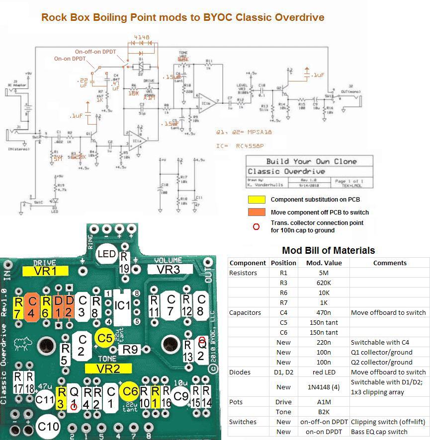
The modified pedal works as expected, and certainly has plenty of gain on tap. The combination of the 1K resistor at R7 and the A1M drive pot raises the circuit's maximum gain factor from the stock TS value of 118 to 1011, a factor of 8.5 increase. From about 2 o'clock and up on the drive pot, it's really more of a distortion pedal than an overdrive, especially with humbuckers. The 220n setting on the EQ switch gives essentially the same bass response as a stock TS circuit, and the 470n setting fattens it up by dropping the bass rolloff frequency from ~720Hz down to ~340Hz. I find that this value sounds good with single coils but starts getting a bit muddy with humbuckers, especially at higher gain settings. Overall, the modified pedal is quite a bit brighter sounding than my stock COD build was, primarily from dropping the two tantalum cap values down to 150n, I think. The higher input impedance from the R1 & R3 substitutions probably have some effect, as well.

The three clipping switch settings sound pretty much as you would expect, with the 1x3 1N4148 diodes giving the most distortion/compression, the LED's less so and noticeably louder, and the middle "diode lift" setting being loudest and least distorted. Bottom line: a brighter and much gainier overdrive pedal with some nice tonal flexibility from the two toggle switches, but still quite clearly a Tube Screamer in character. I certainly don't find anything novel here, but it does what you would expect it to do well enough. And modding a $70 COD kit beats the heck out of dropping $350 on a "real" RBBP. But I still think that the BYOC Overdrive 2 has more to offer, especially with the before-or-after boost wiring mod.

Below is a composite diagram I put together, using a modified version of Guitarmageddon's COD schematic mark-up (thanks, mate!!), along with a color-coded COD board diagram and a "bill of materials" for the mod. I'll add a couple of photos of the modified pedal later....

Image

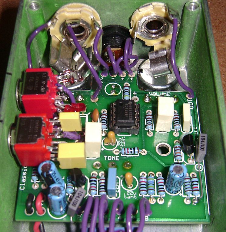
Gut shot showing the various component modifications and the two added toggle switches. Note the two gray box film caps soldered to the buffer transistor collectors on one side, and connected to ground on the other.

Image

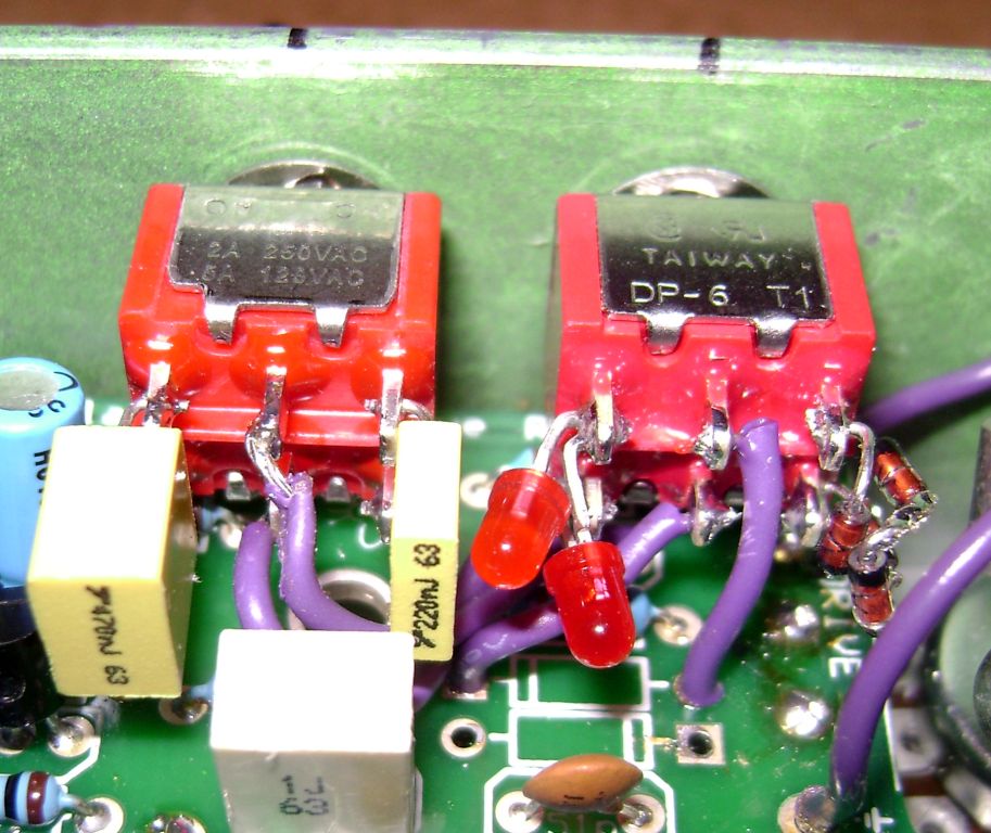
Close-up of the two DPDT mini-toggle switches. The bass EQ switch is on the left, with 220n and 470n caps, and the clipping switch is on the right, with a pair of red LEDs and a 1x3 1N4148 diode array.

Image

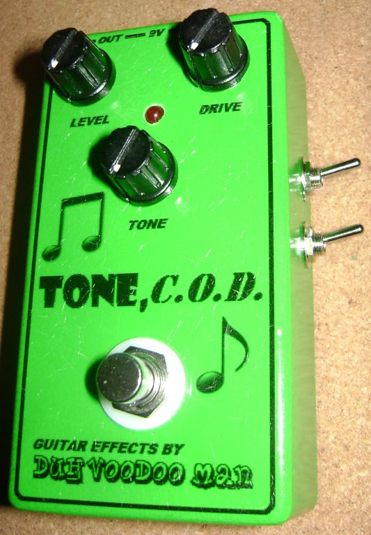
Shot of the enclosure showing the toggle switch placement.

Image

_________________
“My favorite programming language is SOLDER” - Bob Pease (RIP)

My Website * My Musical Gear * My DIY Pedals: Pg.1 - Pg.2


Top
 Profile  
 
PostPosted: Wed Oct 03, 2012 1:05 pm 
Offline
User avatar

Joined: Thu Jul 07, 2011 2:32 am
Posts: 1232
Location: Gillingham UK
Another great experiment Bob! Thanks for sharing. :grin:

_________________
Morgan wrote:
I'd definitely end up gluing my hand to my crotch if I tried that. :shock: :lol:


Top
 Profile  
 
PostPosted: Mon Nov 09, 2015 10:18 am 
Offline

Joined: Mon Jul 27, 2015 9:18 am
Posts: 28
Where is the switch on the left connected to the PCB?


Top
 Profile  
 
PostPosted: Mon Nov 09, 2015 11:05 am 
Offline
Moderator
User avatar

Joined: Tue Jan 02, 2007 1:24 pm
Posts: 16224
Location: Albany, NY
johnboyles wrote:
Where is the switch on the left connected to the PCB?

Assuming that you are referring to the switch on the left in the close-up shot of both switches, i.e. the one with the two yellow film caps soldered on each end, the two center lugs of the switch are connected to the two eyelets for C4 (highlighted in orange on the labeled PCB diagram).

_________________
“My favorite programming language is SOLDER” - Bob Pease (RIP)

My Website * My Musical Gear * My DIY Pedals: Pg.1 - Pg.2


Top
 Profile  
 
PostPosted: Mon Nov 09, 2015 11:59 am 
Offline

Joined: Mon Jul 27, 2015 9:18 am
Posts: 28
Yes - thanks for clarifying. Two more questions:

1) which ground is the new CAP attached to the collector to Q1 tied to? It looks like it goes under the board whereas the other one is tied to R14.
2) it's hard to see the orientation of the diodes. I presume they are in series with the striped end facing down? Also, I think the diode array is in parallel to one of the diodes but I don't understand that? Does that generate asymmetrical clipping? Isn't there a 3-way switch? on/off/on? Where would the distortion come from if the switch was off?

I guess question 2 is really several questions. I'm new to this electronics stuff, I'm a chemist and I only understand electrons from a covalent bond perspective.

Thanks!

John


Top
 Profile  
 
PostPosted: Mon Nov 09, 2015 8:39 pm 
Offline
Moderator
User avatar

Joined: Tue Jan 02, 2007 1:24 pm
Posts: 16224
Location: Albany, NY
johnboyles wrote:
1) which ground is the new CAP attached to the collector to Q1 tied to? It looks like it goes under the board whereas the other one is tied to R14.

As stated in the original post:

"There are also two 100n caps added in mod, running between the collector of each buffer transistor and ground. I just tack-soldered these in place; I used the solder joint for the wire connection for lug 2 of the footswitch as the ground for the input buffer cap, and the bottom eyelet of R14 for the output buffer cap."

I wrapped the cap lead around the edge of the board and tack-soldered it to the joint for the #2 eyelet, which makes the solder connection easy.

johnboyles wrote:
2) it's hard to see the orientation of the diodes. I presume they are in series with the striped end facing down? Also, I think the diode array is in parallel to one of the diodes but I don't understand that? Does that generate asymmetrical clipping? Isn't there a 3-way switch? on/off/on? Where would the distortion come from if the switch was off?

Refer to the Rock Box Boiling Point mods schematic in the original post, since it shows how the diodes are connected. For the 1N4148 silicon diodes, you have 3 diodes connected in series, head to tail, across one pair of end lugs on the toggle switch, and a single diode connected in parallel to those same two lugs, but with the opposite polarity. So you're clipping one side of the audio sine waveform with the three series diodes and the other side of the waveform with the single diode. So, yes, this is indeed asymmetric clipping, since the two nodes of the audio signal are seeing different clipping configurations. The other side of the toggle switch has a pair of red LED's in parallel, again oriented in opposite polarities, for symmetrical clipping. The LED's have a much higher forward voltage threshold than the 1N4148's, so they clip less signal, giving a louder signal with less distortion and compression. The middle position of the toggle isn't connected to either set of clipping diodes (a.k.a. a "diode lift" setting), so will give the loudest, cleanest signal. There is usually still some degree of distortion introduced through the gain imparted by the op amp, or from the strength of the output signal pushing the amplifier into overdrive.

_________________
“My favorite programming language is SOLDER” - Bob Pease (RIP)

My Website * My Musical Gear * My DIY Pedals: Pg.1 - Pg.2


Top
 Profile  
 
PostPosted: Mon Jan 04, 2016 9:32 am 
Offline

Joined: Mon Jul 27, 2015 9:18 am
Posts: 28
Thanks for the detailed explanation. This MOD is killer BTW! I didn't think I could build a pedal that was better than the Fulltone OCD but I think the classic OD (with this MOD) is better. The OCD is just a little harsh in the high frequency. I can't believe I just said that...

This guitar pedal building and tweaking is quite addictive.

Cheers, John


Top
 Profile  
 
PostPosted: Mon Jan 04, 2016 9:57 am 
Offline
Moderator
User avatar

Joined: Tue Jan 02, 2007 1:24 pm
Posts: 16224
Location: Albany, NY
Glad it worked out well for you, John. Thanks for posting this, since it prompted me to fix all of the broken links in my original post due to the forum and BYOC product page URL changes. Now they actually go someplace!

_________________
“My favorite programming language is SOLDER” - Bob Pease (RIP)

My Website * My Musical Gear * My DIY Pedals: Pg.1 - Pg.2


Top
 Profile  
 
PostPosted: Fri Jan 15, 2016 1:00 pm 
Offline

Joined: Sun Jul 19, 2015 9:20 pm
Posts: 23
I am getting an annoying (and undesirable) fizzy distortion in the decay of the guitar signal coming out of the pedal. It is most noticeable when the gain is low and when chords are played. i.e. less noticeable with lead guitar. The fizzy distortion decay is probably just masked with high gain settings... The fizzy distortion happens mostly when the gain switch is in the middle, i.e. only 1 diode. Sounds like the guitar signal is being choked out somehow. Is there a way I can make this go away? Maybe I'm getting a voltage drop in the circuit somewhere?

This would be the best guitar pedal on the planet without this sound. This pedal is so open sounding and clear with a ton of gain and headroom at your fingertips.

Any help is appreciated!

John


Top
 Profile  
 
PostPosted: Fri Jan 15, 2016 2:02 pm 
Offline
Moderator
User avatar

Joined: Tue Jan 02, 2007 1:24 pm
Posts: 16224
Location: Albany, NY
Sounds like there's definitely something wrong in the build. I hear nothing like you describe in my own RBBP mod of the BYOC Classic OD. For one thing, there's no "gain switch"--I assume you are referring to the 3-position clipping switch. Assuming that you followed the schematic and bill of materials shown above, none of the three switch positions involves just a single diode. One "on" position uses a pair of LED's, the other uses a 1x3 1N914 silicon diode array, and the middle "off" position gives no clipping.

I suspect that your problem is somewhere else in the circuit and that the different output levels from the three clipping switch settings makes the "fizz" more or less evident to the ear. You might want to start a new thread in the DIY Discussion sub-forum and post some photos of your build, so that the forum members & moderators can look it over and see if they can spot a problem.

_________________
“My favorite programming language is SOLDER” - Bob Pease (RIP)

My Website * My Musical Gear * My DIY Pedals: Pg.1 - Pg.2


Top
 Profile  
 
Display posts from previous:  Sort by  
Post new topic Reply to topic  [ 10 posts ] 

All times are UTC - 6 hours


Who is online

Users browsing this forum: No registered users and 1 guest


You cannot post new topics in this forum
You cannot reply to topics in this forum
You cannot edit your posts in this forum
You cannot delete your posts in this forum
You cannot post attachments in this forum

Search for:
Jump to:  
cron
Powered by phpBB® Forum Software © phpBB Group