Build Your Own Clone Message Board

It is currently Fri Apr 19, 2024 3:52 pm

All times are UTC - 6 hours


Post new topic Reply to topic  [ 4 posts ] 
Author Message
PostPosted: Fri Apr 30, 2021 6:06 pm 
Offline
User avatar

Joined: Tue Jul 16, 2019 9:44 am
Posts: 27
Hi,
I have read about UV printing on FX enclosures at a couple service provider websites, but they seem to rely on enclosures with differing drill templates than seem common to the BYOC kit line up.

I downloaded the BYOC layout templates, and found them to be fairly generalized, and lacking in the specific dimensions that I would have hoped to find.

It would be incredibly helpful if the BYOC templates had the actual design dimensions, which I assume were referenced from the PCB layout software and the Potentiometer data sheet dimensions.

So, I am writing to ask if there are any UV print service providers who have become familiar with the enclosure layouts that mate well with BYOC circuit boards and board mounted components. In other words, is there a printer service who has specific experience with aligning and registering the layouts for BYOC kits so that I don't have to try and try again in an effort to get good results on my one off hobby builds?

Thank you!


Top
 Profile  
 
PostPosted: Mon May 03, 2021 11:10 am 
Offline
Site Admin
User avatar

Joined: Sun Jan 22, 2006 1:39 pm
Posts: 5991
Location: Richland, WA
http://www.byocelectronics.com/125b.pdf

http://www.byocelectronics.com/125b.ai

Here is the drill template in PDF and Adobe Illustrator forms for our standard 125B layout. This will work for the majority (but not all) of our 125B size kits. If it's a 2-knob kit, leave off 3 of the holes. If it's a 3-knob kit, leave off 2 of the holes. If it's 3 knob and 2 toggles, then make then use all the holes.

_________________
*patience is a virtue*

Please do not PM me. email is prefered. keith@buildyourownclone.com


Top
 Profile  
 
PostPosted: Mon May 03, 2021 11:25 pm 
Offline
User avatar

Joined: Tue Jul 16, 2019 9:44 am
Posts: 27
Hi,
Thank you for posting the files. I just used the .ai example in an effort to determine the coordinates of the centers of the holes and or cross hairs.

What I found is that most of the holes are not aligned with the cross hairs, most of the cross hairs are not aligned with the other cross hairs, and most of the holes are not aligned with the holes.

In other words, these templates might be useful for drilling by hand but they are not accurate enough to take full advantage of computer numerical control machining or printing processes.


I assume that the .ai file document's size was meant to be described in millimeters and that the "panel" measured 62mm x 117mm.

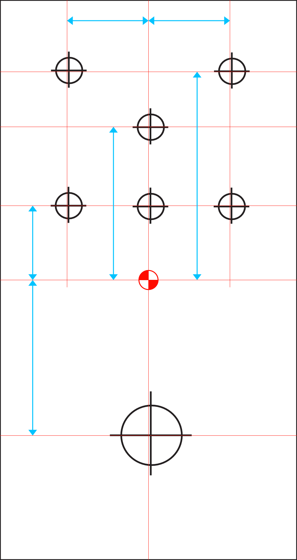
With this in mind, I added a center point on the panel and bisected the vertical and horizontal spans with center lines. Then I added some extra guide lines at arbitrarily chosen positions that seemed reasonably near to the hole centers displayed in the template file.

I exported a large format jpeg of my modifications to the templates and have uploaded it here.

Attachment:
125b-blank.jpg
125b-blank.jpg [ 168.85 KiB | Viewed 2705 times ]


The holes and cross hairs in the original templates seem to be placed with an approximation of alignment.

The picture shows the variances as slight offsets, which can be seen if you zoom in. When I viewed the specific coordinates embedded in the template document it became apparent that very few elements were aligned and I simply had to guess where the intended center points might be when I placed the extra guide lines and dimensions. It was not too difficult once I dug in and got to work, but it did sort of feel like I was reinventing the wheel, as I expect that the PCBs and enclosures are drilled out with specific dimensions. It seems natural to have hoped that a dimensioned drawing could be provided with "official" values rather than the best guess DIY version I have cobbled together.

I think I figured out the info that I had wanted to learn.

It would be useful if there was a BYOC document made public that expresses the intent of the hole placement with the sort of specific dimension labeling that is useful for CNC and digital print type processes.


Thank you!


Top
 Profile  
 
PostPosted: Sun Jan 02, 2022 5:12 pm 
Offline

Joined: Tue Dec 28, 2021 9:03 pm
Posts: 4
Does anyone have a file like that for the Mini pedals? I think they are the 1590a layout. I have a Lil Black Key I'd like to do a design for.

Is there a thread with all these layouts somewhere? I can't find them.

Thanks!!


Top
 Profile  
 
Display posts from previous:  Sort by  
Post new topic Reply to topic  [ 4 posts ] 

All times are UTC - 6 hours


Who is online

Users browsing this forum: No registered users and 1 guest


You cannot post new topics in this forum
You cannot reply to topics in this forum
You cannot edit your posts in this forum
You cannot delete your posts in this forum
You cannot post attachments in this forum

Search for:
Jump to:  
cron
Powered by phpBB® Forum Software © phpBB Group