Build Your Own Clone Message Board

It is currently Thu Apr 18, 2024 11:32 am

All times are UTC - 6 hours


Post new topic Reply to topic  [ 8 posts ] 
Author Message
PostPosted: Tue Jun 30, 2020 4:18 pm 
Offline

Joined: Tue Jun 30, 2020 4:14 pm
Posts: 4
I have a problem with an analog chorus kit I received from you about two months ago. It seems that I have a set of wrong IC's... instead of one 3102 and one 3207 I instead have one MN3101 and one MN3007 but maybe they are interchangeable?
It says rev 1.0 on the top if interested, Hope someone can clear up my confusion :)


Top
 Profile  
 
PostPosted: Tue Jun 30, 2020 4:27 pm 
Offline
Site Admin
User avatar

Joined: Sun Jan 22, 2006 1:39 pm
Posts: 5991
Location: Richland, WA
Can you post a pic of your PCB?

_________________
*patience is a virtue*

Please do not PM me. email is prefered. keith@buildyourownclone.com


Top
 Profile  
 
PostPosted: Wed Jul 01, 2020 5:37 am 
Offline

Joined: Tue Jun 30, 2020 4:14 pm
Posts: 4
Yes of course.
Here is a picture of the PCB and the received IC's.
As you can see i already soldered all the resistors.


Attachments:
2.jpg
2.jpg [ 407.67 KiB | Viewed 2546 times ]
1.jpg
1.jpg [ 462.68 KiB | Viewed 2546 times ]
Top
 Profile  
 
PostPosted: Wed Jul 01, 2020 6:53 am 
Offline
Moderator
User avatar

Joined: Tue Feb 09, 2010 4:45 pm
Posts: 4691
Location: Rochester, NY
I'll let Keith comment on the components, but I'd like to give you a quick heads-up that you probably aren't using enough solder, or aren't applying it correctly. (It's hard to tell which without seeing the other side of the board.) The PCB eyelets should be filled with solder. On boards like this, the solder will flow through from the back side to the component side if enough solder is applied correctly. Something to keep in mind as you proceed with your build.

_________________
Scott

My band, Austin Hollow


Top
 Profile  
 
PostPosted: Wed Jul 01, 2020 9:09 am 
Offline

Joined: Tue Jun 30, 2020 4:14 pm
Posts: 4
Thanks for the heads up, here is a pic of the backside, does it look alright or all wrong?


Attachments:
105964359_270521270922098_4751548213827742397_n.jpg
105964359_270521270922098_4751548213827742397_n.jpg [ 731.2 KiB | Viewed 2528 times ]
Top
 Profile  
 
PostPosted: Wed Jul 01, 2020 9:45 am 
Offline
Moderator
User avatar

Joined: Tue Feb 09, 2010 4:45 pm
Posts: 4691
Location: Rochester, NY
Thanks for uploading that. You probably want to take some time to clean up your soldering, and maybe even get some inexpensive parts to practice with.

I've marked up your photo:

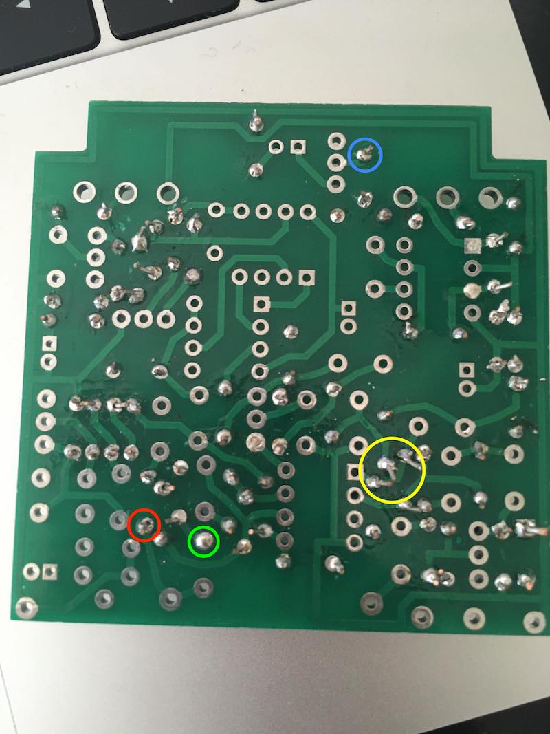
The red circle is a joint that needs more solder; notice the eyelet is not full, even on the solder side.
The yellow circle is a few of many joints that need to have the component leads clipped back closer to the board to avoid shorts.
The blue circle is a joint that looks "cold"; it is a misshapen blob rather than a nice tight cone. (It also needs the lead cut shorter.)
The green circle is closer to what you're going for, with the caveat that it's a little blurry, so I may be missing something.

If you haven't already done it, I'd recommend looking on YouTube for some video tutorials on soldering through-hole PCBs. If nothing more, it will give you examples of what to shoot for. Also, read through Stephen's Tips For A Successful Build. Some of the info is not pertinent to every build, but it's got great suggestions with lots of example photos.

Let me know if you have any questions!

Attachment:
PCB marked up.jpg
PCB marked up.jpg [ 89.96 KiB | Viewed 2523 times ]

_________________
Scott

My band, Austin Hollow


Top
 Profile  
 
PostPosted: Wed Jul 01, 2020 9:51 am 
Offline
Moderator
User avatar

Joined: Tue Jan 02, 2007 1:24 pm
Posts: 16217
Location: Albany, NY
1) Your kit is fine--you just have an older version of the PCB when a different chip set was being used. I would guess this is due to purchasing it from a European seller having some older kits in stock. If you take a look at the PCB diagrams in the latter part of the instructions (pg. 24 is a good example), you'll see that the rev.1.0 board is pictured and the silkscreen labeling of the two IC's in question match the ones you received in the kit. So you are good to go.

2) I agree completely with Scott's comments about the quality of your soldering. I suspect that you are using lead-free solder because that's all that's available in Europe due to the RoHS laws. This solder is harder to work with and takes more heat to get good flow and wetting. I would strongly suggest that you go back through your resistors and apply more heat and a bit more solder to most of your joints. The solder should completely cover the solder pad on the PCB, there should be no holes/voids in the joint, and solder should be visible poking through the eyelet on the component side of the board. You should also trim the component leads right down to the tops of their respective solder joints to minimize the chance of unintended shorts. Here are some links for additional information and guidance on good soldering quality:

viewtopic.php?f=9&t=52211

viewtopic.php?f=9&t=6401

viewtopic.php?f=9&t=52188

_________________
“My favorite programming language is SOLDER” - Bob Pease (RIP)

My Website * My Musical Gear * My DIY Pedals: Pg.1 - Pg.2


Top
 Profile  
 
PostPosted: Wed Jul 01, 2020 1:24 pm 
Offline

Joined: Tue Jun 30, 2020 4:14 pm
Posts: 4
Thank you very much for clearing that up, and helping me with my soldering technique as well !


Top
 Profile  
 
Display posts from previous:  Sort by  
Post new topic Reply to topic  [ 8 posts ] 

All times are UTC - 6 hours


Who is online

Users browsing this forum: No registered users and 1 guest


You cannot post new topics in this forum
You cannot reply to topics in this forum
You cannot edit your posts in this forum
You cannot delete your posts in this forum
You cannot post attachments in this forum

Search for:
Jump to:  
cron
Powered by phpBB® Forum Software © phpBB Group