Build Your Own Clone Message Board

It is currently Thu May 02, 2024 8:30 pm

All times are UTC - 6 hours


Post new topic Reply to topic  [ 7 posts ] 
Author Message
PostPosted: Thu Feb 11, 2021 10:29 am 
Offline

Joined: Thu Feb 11, 2021 9:31 am
Posts: 4
Hey Everyone,

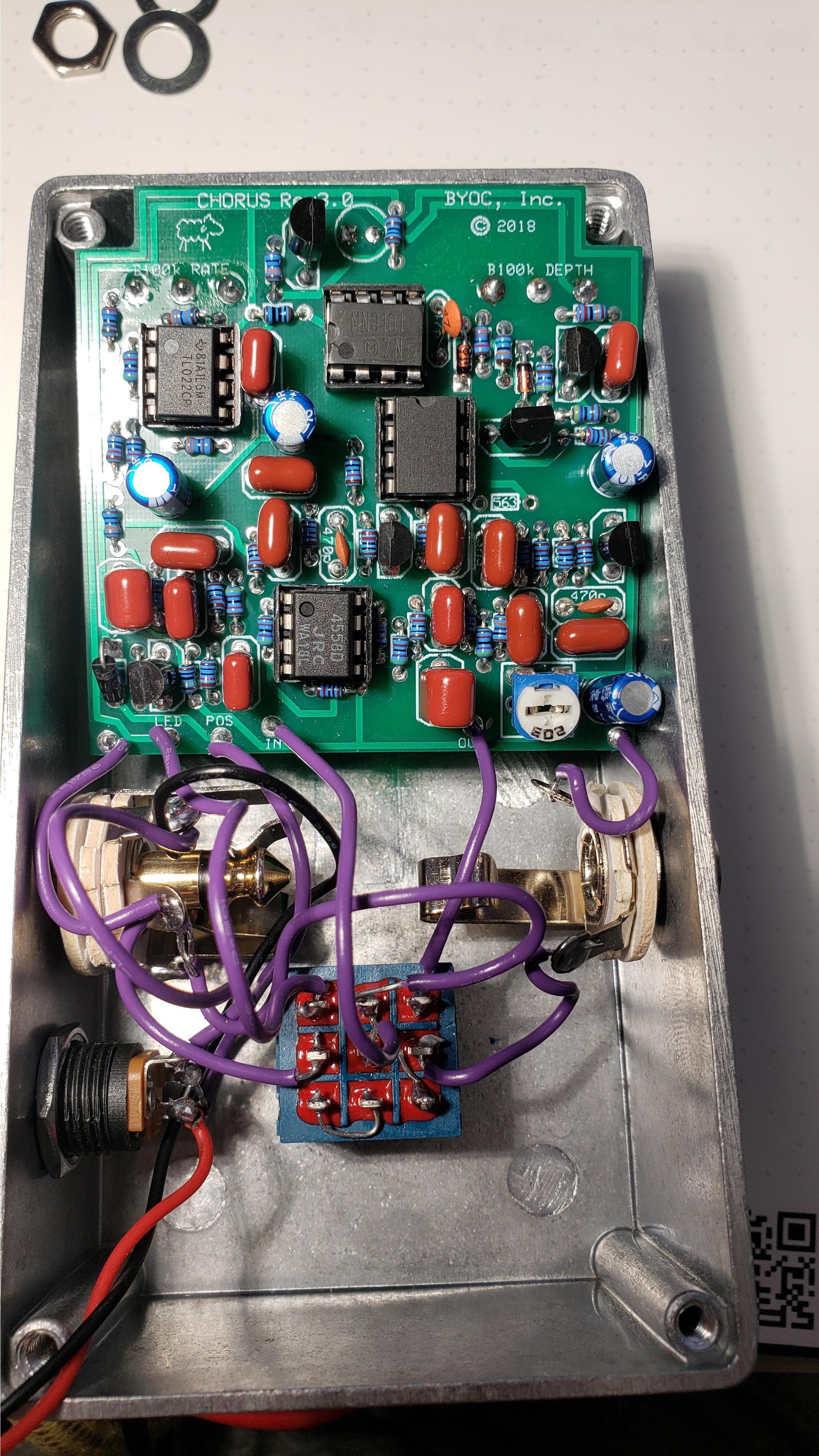
Just finished my first ever pedal build last night (should've started with a Fuzz, lol). It's been a while since I've soldered so maybe I have a cold joint. I have the 3007 3.0 chipset, I made sure to follow the instructions for tack soldering the 56k resistor across the pins on the back. One thing I know I went off the rails for, I installed the 4558 socket backwards (I missed the instruction on aligning the notch, luckily the other 3 chips I got in the right way). I tried for a while to desolder and reverse the socket but just couldn't get that thing out. I just went ahead and installed the 4558 chip the right way and hoped this would work. This was all before any power was applied. I'm not finding any continuity between any of the 3 legs on the 25k Bias Pot Voltage, could this be the culprit? Readings on the chips below, answers to the support post questions and links to photos follow.

3007
Pin 1: 8.4
Pin 2: 4.4
Pin 3: 3.5
Pin 4: 0.6
Pin 5: 0.0
Pin 6: 4.3
Pin 7: 4.1
Pin 8: 4.1
3101
Pin 1: 8.2 - 8.4 (smooth sweep)
Pin 2: 4.3
Pin 3: 0.0
Pin 4: 4.3
Pin 5: 2.7 - 3.7 (smooth sweep)
Pin 6: 7.1 - 7.4 (smooth sweep)
Pin 7: 2.4 - 2.8 (smooth sweep)
Pin 8: 0.5
4558
Pin 1: 4.2
Pin 2: 4.2
Pin 3: 4.2
Pin 4: 0.0
Pin 5: 4.2
Pin 6: 4.2
Pin 7: 4.2
Pin 8: 8.5
TL022
Pin 1: .6 - 7.8 (bouncing back and forth)
Pin 2: 4.1 - 4.4 (smooth sweep)
Pin 3: 1.7 - 6.6 (smooth sweep)
Pin 4: 0.0
Pin 5: 4.0 - 4.4 (smooth sweep)
Pin 6: 4.5
Pin 7: 2.0 - 6.5 (smooth sweep)
Pin 8: 8.5

1. Picture of the top side of your PCB.
https://u.cubeupload.com/solarsamurai/B ... usTopP.jpg
2. Picture of the underside of your PCB.
https://u.cubeupload.com/solarsamurai/B ... usBott.jpg
https://u.cubeupload.com/solarsamurai/2 ... usBott.jpg
3. Picture that clearly shows your footswitch/jack wiring and the wires going to the PCB
https://u.cubeupload.com/solarsamurai/B ... usTopP.jpg
4. Picture that clearly shows your wiring going from the PCB to the off board components
https://u.cubeupload.com/solarsamurai/B ... usTopP.jpg
5. Is bypass working?
Yes
6. Does the LED come on?
Yes and reacts to the rate knob.
7. If you answer yes to 5 and 6, what does the pedal do when it is "on"? Please be as specific as possible.
Pushes through clean signal with 0 noise, very clear sound.
8. Do all of the controls work properly? Just 1 or 2 not working?
No
9. Does the problem change if you switch from battery to a power supply or visa versa.
Problem persists through battery and power supply operation.


Top
 Profile  
 
PostPosted: Thu Feb 11, 2021 11:59 am 
Offline
Site Admin
User avatar

Joined: Sun Jan 22, 2006 1:39 pm
Posts: 5992
Location: Richland, WA
It doesn't matter if the socket is backwards as long as you put the chip in correctly. The 4558 is in charge of the dry signal, so if you're getting clean unaffected signal when the pedal is on, then the 4558 is working. The 4558 voltages look good too. In fact, all of your voltages look good which would suggest that you simply have a cold solder joint somewhere in the wet signal path. Does the rate of the LED blinking change with the speed knob?

My first suggestion would be to reflow all of the solder joints on your PCB.

_________________
*patience is a virtue*

Please do not PM me. email is prefered. keith@buildyourownclone.com


Top
 Profile  
 
PostPosted: Thu Feb 11, 2021 1:00 pm 
Offline
Moderator
User avatar

Joined: Tue Jan 02, 2007 1:24 pm
Posts: 16235
Location: Albany, NY
solarsamurai wrote:
...I'm not finding any continuity between any of the 3 legs on the 25k Bias Pot Voltage, could this be the culprit?

Not surprising, unless you happened to have the trimpot turned fully CW or CCW. This bias pot functions as a voltage divider--one outer leg connects to your power source (V+) and the other outer leg to ground. If you measure the resistance between these outer legs (with power disconnected), the result should be right about 25 Kohms. The middle leg (a.k.a. the "wiper") is what then provides the bias voltage to various points in the effect circuit--more or less depending upon where you have the trimpot set in its sweep arc. As the instructions note (pg. 15), the optimal setting should be very close to the middle of the trimpot sweep, at which point half of the supply voltage is directed to the effect circuit connections and the other half to ground. You then "tweak" the setting to get the best/cleanest chorus effect.

At that midpoint setting, there should be ~12.5 Kohms resistance between the middle leg and either of the two outer legs. You will only find continuity (i.e. near-zero resistance) between the middle leg and one of the outside legs if the trimpot is set at one or the other extreme end of its travel. At such a setting, the resistance to the opposite outer leg will be the full resistance of the pot, ~25 Kohms.

Hope that helps explain what's happening with the trimpot in this circuit.

_________________
“My favorite programming language is SOLDER” - Bob Pease (RIP)

My Website * My Musical Gear * My DIY Pedals: Pg.1 - Pg.2


Top
 Profile  
 
PostPosted: Thu Feb 11, 2021 2:00 pm 
Offline

Joined: Thu Feb 11, 2021 9:31 am
Posts: 4
byoc wrote:
It doesn't matter if the socket is backwards as long as you put the chip in correctly. The 4558 is in charge of the dry signal, so if you're getting clean unaffected signal when the pedal is on, then the 4558 is working. The 4558 voltages look good too. In fact, all of your voltages look good which would suggest that you simply have a cold solder joint somewhere in the wet signal path. Does the rate of the LED blinking change with the speed knob?

My first suggestion would be to reflow all of the solder joints on your PCB.


Right, the LED matches up with the speed knob adjustments. Does this mean the LFO & Clock Driver circuit is functioning correctly? (Sorry, I'm more of an electrician than an electronic tech) I'll re-flow tonight and see if I can get it up and running. Thanks for the help.


Top
 Profile  
 
PostPosted: Thu Feb 11, 2021 2:03 pm 
Offline

Joined: Thu Feb 11, 2021 9:31 am
Posts: 4
duhvoodooman wrote:
solarsamurai wrote:
...I'm not finding any continuity between any of the 3 legs on the 25k Bias Pot Voltage, could this be the culprit?

Not surprising, unless you happened to have the trimpot turned fully CW or CCW. This bias pot functions as a voltage divider--one outer leg connects to your power source (V+) and the other outer leg to ground. If you measure the resistance between these outer legs (with power disconnected), the result should be right about 25 Kohms. The middle leg (a.k.a. the "wiper") is what then provides the bias voltage to various points in the effect circuit--more or less depending upon where you have the trimpot set in its sweep arc. As the instructions note (pg. 15), the optimal setting should be very close to the middle of the trimpot sweep, at which point half of the supply voltage is directed to the effect circuit connections and the other half to ground. You then "tweak" the setting to get the best/cleanest chorus effect.

At that midpoint setting, there should be ~12.5 Kohms resistance between the middle leg and either of the two outer legs. You will only find continuity (i.e. near-zero resistance) between the middle leg and one of the outside legs if the trimpot is set at one or the other extreme end of its travel. At such a setting, the resistance to the opposite outer leg will be the full resistance of the pot, ~25 Kohms.

Hope that helps explain what's happening with the trimpot in this circuit.


Hey thanks for this explanation!


Top
 Profile  
 
PostPosted: Fri Feb 12, 2021 11:59 am 
Offline

Joined: Thu Feb 11, 2021 9:31 am
Posts: 4
solarsamurai wrote:
byoc wrote:
It doesn't matter if the socket is backwards as long as you put the chip in correctly. The 4558 is in charge of the dry signal, so if you're getting clean unaffected signal when the pedal is on, then the 4558 is working. The 4558 voltages look good too. In fact, all of your voltages look good which would suggest that you simply have a cold solder joint somewhere in the wet signal path. Does the rate of the LED blinking change with the speed knob?

My first suggestion would be to reflow all of the solder joints on your PCB.


Right, the LED matches up with the speed knob adjustments. Does this mean the LFO & Clock Driver circuit is functioning correctly? (Sorry, I'm more of an electrician than an electronic tech) I'll re-flow tonight and see if I can get it up and running. Thanks for the help.


So I reflowed the solder joints and now everything works. Thanks!


Top
 Profile  
 
PostPosted: Fri Feb 12, 2021 12:47 pm 
Offline
Moderator
User avatar

Joined: Tue Jan 02, 2007 1:24 pm
Posts: 16235
Location: Albany, NY
solarsamurai wrote:
So I reflowed the solder joints and now everything works. Thanks!

Nice! It's amazing how often this simple process solves "no effect" problems. Enjoy your new pedal! :mrgreen:

_________________
“My favorite programming language is SOLDER” - Bob Pease (RIP)

My Website * My Musical Gear * My DIY Pedals: Pg.1 - Pg.2


Top
 Profile  
 
Display posts from previous:  Sort by  
Post new topic Reply to topic  [ 7 posts ] 

All times are UTC - 6 hours


Who is online

Users browsing this forum: No registered users and 3 guests


You cannot post new topics in this forum
You cannot reply to topics in this forum
You cannot edit your posts in this forum
You cannot delete your posts in this forum
You cannot post attachments in this forum

Search for:
Jump to:  
Powered by phpBB® Forum Software © phpBB Group