Build Your Own Clone Message Board

It is currently Fri Apr 19, 2024 12:12 pm

All times are UTC - 6 hours


Post new topic Reply to topic  [ 13 posts ] 
Author Message
PostPosted: Tue May 17, 2022 12:22 am 
Offline

Joined: Tue May 17, 2022 12:00 am
Posts: 7
Attachment:
File comment: Solder side of PCB.
IMG-4990.jpg
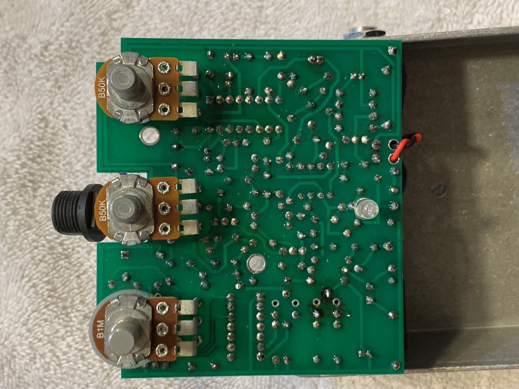
IMG-4990.jpg [ 262.59 KiB | Viewed 2672 times ]
Attachment:
File comment: Component side of PCB.
IMG-4989.jpg
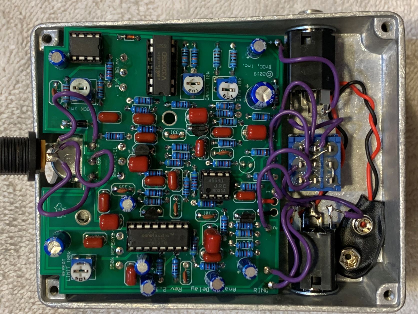
IMG-4989.jpg [ 367.88 KiB | Viewed 2672 times ]


The pedal passes dry signal whether the footswitch is engaged or not. The LED comes on when the footswitch is engaged. When the pedal is on, the pots and trimpots have no effect on the signal, it's just a dry signal the same as when in bypass. The pedal behaves the same when using a 9V battery as well as a 9V 100mA isolated power output.

I initially had some trouble with the bias trimpot (plastic part broke), and had to replace it, but this didn't resolve the issue. I had a bit of a hard time soldering when replacing the trimpot, but the connections appear to be good.

This is my 4th pedal build and I've never had any issues, but I don't know enough about circuit design or analysis to even know where to begin. I've double checked all the components for proper placement and orientation, as well as hookup wire connections and everything appears to be correct.

I have an old multimeter, though its functionality is quite questionable, but I don't know what to check, or how to check it.

Thanks!


Top
 Profile  
 
PostPosted: Tue May 17, 2022 10:39 am 
Offline
Moderator
User avatar

Joined: Tue Jan 02, 2007 1:24 pm
Posts: 16222
Location: Albany, NY
I don't see anything misplaced and your soldering quality looks quite good, so I would recommend two things. Both require a reliable multimeter:

  1. Take a complete set of DC voltage readings on the pins of all four IC's. To do this, set your multimeter to the DC voltage mode, indicated by a solid line above a dotted one. Use the 20VDC range setting if it's not an auto-ranging meter. Your power source needs to be connected and there must be a cable in the input jack. If the pedal is assembled into the metal enclosure, put the black probe into one of the corner screw bosses of the enclosure--this is your required ground connection. If the "guts" are out of the enclosure, use the sleeve tab of the input jack for the ground connection. Then touch the red probe to each point that you want to measure. See the image below for the numbering of the pins; with the IC marker dot or indentation on the left, pin 1 is at the bottom left and the numbers increase in a counter-clockwise direction around the IC.

    Image

    For comparison, here are the pin voltages that I see on my own fully functional Analog Delay:

    Attachment:
    ADv2_IC_voltages.gif
    ADv2_IC_voltages.gif [ 10.88 KiB | Viewed 2643 times ]

  2. Since you replaced the bias trimpot and noted some difficulty in doing so, it would be worthwhile to confirm continuity between the trimpot solder joints and the components they should be connected to. I have attached a marked up image of the AD PCB below indicating the pairs of solder joints that should have continuity, i.e. a direct connection between them. To measure continuity, set your meter to the continuity mode, usually indicated by an icon that looks like sound waves emanating from a point. Test the meter by touching the two probes together--this should cause an audible beep/tone from the meter. Then test the continuity of those pairs of joints by simultaneously touching one of the meter probes to each, listening for the desired beep.

    If your meter lacks a continuity mode, you can still determine it by using the meter's resistance mode. Set the meter to its lowest resistance range setting and measure between those same pairs of points. Continuity just means a direct connection with almost no resistance, so you should get a reading of a couple of ohms, at the most.

_________________
“My favorite programming language is SOLDER” - Bob Pease (RIP)

My Website * My Musical Gear * My DIY Pedals: Pg.1 - Pg.2


Top
 Profile  
 
PostPosted: Fri May 20, 2022 7:17 pm 
Offline

Joined: Tue May 17, 2022 12:00 am
Posts: 7
Thanks for the instructions, I was able to get a complete set of voltage readings. The main discrepancies I'm seeing are with the 3205 and pin 16 of the 571, though I'm not sure what would actually indicate an issue or how I'd resolve it.

I couldn't find the marked up image to check continuity, but I'm new to the forum so if it's somewhere I'm just not finding it please let me know. I did check the connection of the bias trimpot and it appears to be good.

Thanks!


Attachments:
File comment: IC Voltage Readings
Screenshot 2022-05-20 201309.jpg
Screenshot 2022-05-20 201309.jpg [ 59.87 KiB | Viewed 2580 times ]
Top
 Profile  
 
PostPosted: Mon May 23, 2022 11:23 am 
Offline
Site Admin
User avatar

Joined: Sun Jan 22, 2006 1:39 pm
Posts: 5991
Location: Richland, WA
Are you able to adjust the voltage of pin 13 of the 3205 with the bias trimmer? If so, what range do you get? What is the voltage range of pin 13 if you take the chip out of the socket?

_________________
*patience is a virtue*

Please do not PM me. email is prefered. keith@buildyourownclone.com


Top
 Profile  
 
PostPosted: Mon May 23, 2022 11:37 am 
Offline
Moderator
User avatar

Joined: Tue Jan 02, 2007 1:24 pm
Posts: 16222
Location: Albany, NY
How were you powering the pedal? Your power source looks to be barely producing 8V.

_________________
“My favorite programming language is SOLDER” - Bob Pease (RIP)

My Website * My Musical Gear * My DIY Pedals: Pg.1 - Pg.2


Top
 Profile  
 
PostPosted: Mon May 23, 2022 12:18 pm 
Offline

Joined: Tue May 17, 2022 12:00 am
Posts: 7
duhvoodooman wrote:
How were you powering the pedal? Your power source looks to be barely producing 8V.


I was using a battery but I've switched over to my power supply (1 Spot Pro CS12 - 9Vdc 100mA outlet, the power supply is connected through a surge protector if that matters) and taken another set of voltages.

All initial measurements were done with all the trimpots at noon.

byoc wrote:
Are you able to adjust the voltage of pin 13 of the 3205 with the bias trimmer? If so, what range do you get? What is the voltage range of pin 13 if you take the chip out of the socket?


For the pin 13 range values the ranges are listed as fully counter-clockwise to fully clockwise.

My multimeter appears to be giving consistent values but it is an older one from harbor freight.

Thanks!


Attachments:
File comment: New Set of Voltage Readings
Screenshot 2022-05-23 131719.jpg
Screenshot 2022-05-23 131719.jpg [ 64.63 KiB | Viewed 2522 times ]
Top
 Profile  
 
PostPosted: Mon May 23, 2022 1:45 pm 
Offline
Site Admin
User avatar

Joined: Sun Jan 22, 2006 1:39 pm
Posts: 5991
Location: Richland, WA
The problem is with your bias voltage to pin 13 (it's actually pin 7 on the data sheet) of the 3205. I would suspect your trimpot isn't working, but it could be that you have a cold solder joint that connects the ground end of the trimmer.

_________________
*patience is a virtue*

Please do not PM me. email is prefered. keith@buildyourownclone.com


Top
 Profile  
 
PostPosted: Mon May 23, 2022 1:53 pm 
Offline

Joined: Tue May 17, 2022 12:00 am
Posts: 7
byoc wrote:
The problem is with your bias voltage to pin 13 (it's actually pin 7 on the data sheet) of the 3205. I would suspect your trimpot isn't working, but it could be that you have a cold solder joint that connects the ground end of the trimmer.


I replaced the bias trimpot once already so the solder joints on it could be the issue. Or it could be that I messed up the trimpot while soldering it.

How can I check if the trimpot is still any good or if I need to replace it?

Thanks!


Top
 Profile  
 
PostPosted: Mon May 23, 2022 2:31 pm 
Offline
Site Admin
User avatar

Joined: Sun Jan 22, 2006 1:39 pm
Posts: 5991
Location: Richland, WA
hchildre wrote:
byoc wrote:
The problem is with your bias voltage to pin 13 (it's actually pin 7 on the data sheet) of the 3205. I would suspect your trimpot isn't working, but it could be that you have a cold solder joint that connects the ground end of the trimmer.


I replaced the bias trimpot once already so the solder joints on it could be the issue. Or it could be that I messed up the trimpot while soldering it.

How can I check if the trimpot is still any good or if I need to replace it?

Thanks!


Measure the resistance between the two outer legs. That should measure at whatever the trimmer is supposed to be, in this case 100k. Then measure the center leg to one of the outer lugs. It should measure 0 - 100k as you turn the knob. Then measure the center leg against the other outer leg. It should do the same thing, but in reverse, i.e., if one measures 0 - 100k, the other should measure 100k - 0.

_________________
*patience is a virtue*

Please do not PM me. email is prefered. keith@buildyourownclone.com


Top
 Profile  
 
PostPosted: Mon May 23, 2022 2:53 pm 
Offline

Joined: Tue May 17, 2022 12:00 am
Posts: 7
As you can see I've botched this pretty well. I cleaned the back side with alcohol to try to redo the center leg, and I couldn't even find the solder pad. I'm not sure if it's melted or pushed into the board or what. I tried soldering from the front which burned several components, and then when I tried from the back again, I accidentally pushed a bunch of solder through. When I went to try to adjust the bias the plastic piece snapped off.

The good news is I'm now getting an effect, so that was the culprit, but how would you recommend I proceed? If I replace the trimpot again I'm worried about being able to get it on the board since the first replacement didn't go well, but if I leave it will the globs of solder (particularly in direct contact with the neighboring resistor) cause issues? I must admit I'm a complete novice with removing solder, I have no idea how to do that well.

Thanks!


Attachments:
IMG_5002.jpg
IMG_5002.jpg [ 299.52 KiB | Viewed 2513 times ]
IMG_4999.jpg
IMG_4999.jpg [ 218.78 KiB | Viewed 2513 times ]
Top
 Profile  
 
PostPosted: Tue May 24, 2022 10:22 am 
Offline
Site Admin
User avatar

Joined: Sun Jan 22, 2006 1:39 pm
Posts: 5991
Location: Richland, WA
If you want to replace it, I would suggest nibbing away most of the trimmer with a pair of clippers till just the legs are left still in the PCB. Then with a pair of pliers or tweezers or something like that, heat the solder joints of the remaining legs and gently pull them out, one by one. The the old trimmer removed, it will be much easier to desolder and clean out the eyelets.

I suggest doing it like this with any component you are desoldering that has more than 2 legs and you don't intend on reusing.

_________________
*patience is a virtue*

Please do not PM me. email is prefered. keith@buildyourownclone.com


Top
 Profile  
 
PostPosted: Mon Nov 27, 2023 11:29 am 
Offline

Joined: Sat Jan 02, 2010 11:11 pm
Posts: 14
Hi, I have the same problem with my analog delay and would like to check the pin voltages, but I can't see the pin numbering image. Could you re-post it please? Thanks!


Top
 Profile  
 
PostPosted: Mon Nov 27, 2023 11:45 am 
Offline
Moderator
User avatar

Joined: Tue Jan 02, 2007 1:24 pm
Posts: 16222
Location: Albany, NY
jady wrote:
Hi, I have the same problem with my analog delay and would like to check the pin voltages, but I can't see the pin numbering image. Could you re-post it please? Thanks!

Done.

If your problem persists, please start a new thread here for further assistance.

_________________
“My favorite programming language is SOLDER” - Bob Pease (RIP)

My Website * My Musical Gear * My DIY Pedals: Pg.1 - Pg.2


Top
 Profile  
 
Display posts from previous:  Sort by  
Post new topic Reply to topic  [ 13 posts ] 

All times are UTC - 6 hours


Who is online

Users browsing this forum: No registered users and 1 guest


You cannot post new topics in this forum
You cannot reply to topics in this forum
You cannot edit your posts in this forum
You cannot delete your posts in this forum
You cannot post attachments in this forum

Search for:
Jump to:  
Powered by phpBB® Forum Software © phpBB Group