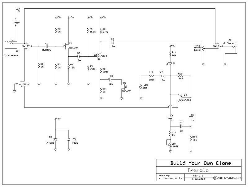
Schematic errata:
1. 10k and LED are switched. LED is actually between 10k and 2N5088 collector.
2. LED is drawn backwards. Anode must be positive w.r.t. cathode to forward bias LED (light).
3. 10 uF cap is not needed as drawn and built - the .22 uF in series makes the combo 0.21 uF, and thus the 10 uF is redundant (see pcb errata below).
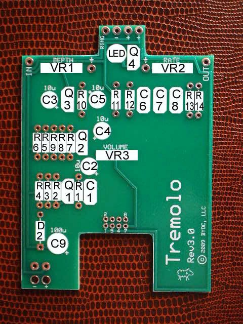
Circuit board errata:
1. 0.47 uF cap C8 footprint is backwards. Install with "+" to (-) side of cap. (schematic shows correct polarity but pcb symbol footprint is reversed from the schematic).
2. 10 uF cap does nothing. In series with the .22 uF, it makes the series combination 0.21 uF. May as well replace the 10uF cap with a wire jumper. The 0.22 uF is enough coupling capacitance to keep the bass roll-off well below 20 Hz (if you take the input R of the next stage to be approx 118k (R5 || R6), a close enough estimate). A better use, IMHO, for the 10 uF is bulk decoupling between 9v and ground. I also put a small ceramic cap (47 pF) where the 9v and ground enter the board to reject rf on the external supply lead.
...more to come as I find them.
Just trying to help for accuracy - not trying to nitpick or critisize... comments welcome.