Build Your Own Clone Message Board

It is currently Sun May 19, 2024 8:07 am

All times are UTC - 6 hours


Post new topic Reply to topic  [ 12 posts ] 
Author Message
PostPosted: Mon Jul 02, 2007 12:11 pm 
Offline

Joined: Wed May 31, 2006 1:45 pm
Posts: 125
Okay, one for the BYOC old timers. I've got one of the old OC44-based Rangemaster kits, wired like so for negative ground:

Image

I've added a 6-way input cap selector and I'm planning to add 1M resistors to ground at the imput and output to eliminate the loud BANG that I get turning it on! My question is this. If I want to add a power diode like an 1N4002 to protect against reverse polarity (like the one on the Ultimate Fuzz), where would I put it?


Last edited by Paladin2019 on Fri Jul 06, 2007 4:54 pm, edited 1 time in total.

Top
 Profile  
 
 Post subject:
PostPosted: Mon Jul 02, 2007 1:15 pm 
Offline

Joined: Fri Mar 30, 2007 5:01 am
Posts: 20
Location: Wishaw, Scotland
Hi Palladin

You had the good grace to answer my post so hopefully this'll help!

Check out the link below on Fuzz Central. It gives the schematic for a NPN Rangemaster with the diode in parallel with the power supply.
Fuzzcentral

Is this diode really essential? I was on building the Rangemaster myself but was going to leave this mod out.


Top
 Profile  
 
 Post subject:
PostPosted: Mon Jul 02, 2007 2:31 pm 
Offline
Moderator
User avatar

Joined: Sat Mar 04, 2006 9:15 pm
Posts: 7662
Location: Ohio
Here's a Rangemaster PCB from GGG that I put together for a guy I know. I used two 2.2M pulldown resistors that can be removed if not needed. I've heard some folks say that they hear an increase in overall brightness of the sound when pulldowns are used. I've never needed them myself since I don't have any popping issues. One thing you might want to consider adding is the Ge diode across the emitter and base of the GE tranny. This provides thermal stability for the tranny so that heat won't have an adverse affect on the sound. Something Ge devices are known for. I've also socketed the input cap so you can either use a rotary switch to dial in more or less lows or to directly insert a value not used in the rotary switch.

Image

This is the rotary switch used to change input caps. The values I chose to go with are .002uf, .003uf, .005uf (stock Rangemaster value), .01uf and .022uf

Image

_________________
"It’s your soldering."


Top
 Profile  
 
 Post subject:
PostPosted: Mon Jul 02, 2007 4:01 pm 
Offline

Joined: Wed May 31, 2006 1:45 pm
Posts: 125
FiercelyFuzzy wrote:

Check out the link below on Fuzz Central. It gives the schematic for a NPN Rangemaster with the diode in parallel with the power supply.
Fuzzcentral

Is this diode really essential? I was on building the Rangemaster myself but was going to leave this mod out.


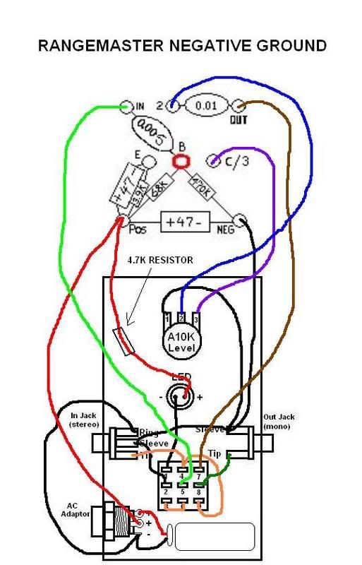
Thanks for that! Unfortunately mine is PNP wired negative so I'm still a bit confused because it's sort of a mix between the two. What I really need to know is what direction the diode needs to face to ground, and where in the circuit to stick the other end.

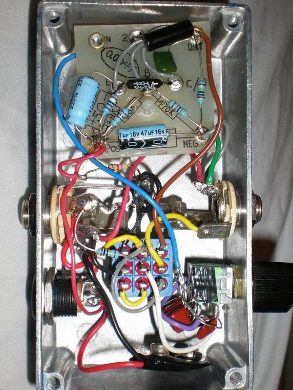
It's definately not an essential mod, mine has been running for years without it and most clones don't seem to have it but my understanding is that it would be better to have it than not so I thought I'd stick it in while I had the box open.

Stephen - Nice work, I hadn't considered putting a diode there. Does it affect the sound? Can you use it on similar Ge devices (fuzzes) without messing things up?

I think a little extra brightness in a treble boost won't be a bad thing, so I'll use the pulldowns. The pop really is quite bad in my unit so I'll accept it as a tradeoff.

My input cap values are, rolling back: 0.0047 (stock), 0.0068, 0.01, 0.022, 0.033 and 0.047 (full range). I think it gives a nice spread. I didn't go for anything smaller than stock because I found the stock value too piercing to use with my tele and the original idea was to have more lows to even things out a bit when changing guitars.


Top
 Profile  
 
 Post subject:
PostPosted: Mon Jul 02, 2007 5:37 pm 
Offline
Moderator
User avatar

Joined: Sat Mar 04, 2006 9:15 pm
Posts: 7662
Location: Ohio
Paladin2019 wrote:
Stephen - Nice work, I hadn't considered putting a diode there. Does it affect the sound? Can you use it on similar Ge devices (fuzzes) without messing things up?

I think a little extra brightness in a treble boost won't be a bad thing, so I'll use the pulldowns. The pop really is quite bad in my unit so I'll accept it as a tradeoff.

My input cap values are, rolling back: 0.0047 (stock), 0.0068, 0.01, 0.022, 0.033 and 0.047 (full range). I think it gives a nice spread. I didn't go for anything smaller than stock because I found the stock value too piercing to use with my tele and the original idea was to have more lows to even things out a bit when changing guitars.

The added diode makes no audible difference that I can hear. As for using it with other Ge devices I don't see any reason why it wouldn't.

I went with the lower cap values strictly for use with humbuckers. These values thin out the sound giving humbuckers a quasi single coil kind of sound. Sort of the way the higher values fatten up single coils to an almost humbucker kind of sound.

_________________
"It’s your soldering."


Top
 Profile  
 
 Post subject:
PostPosted: Wed Jul 04, 2007 4:56 pm 
Offline

Joined: Wed May 31, 2006 1:45 pm
Posts: 125
Right, according to that fuzzcentral article the power diode should be parallel to the power supply. In the diagram in my post above, it looks like it should go from ground, point towards the circuit and go in at the bottom left of the board (POS).

Does that sound right?


Top
 Profile  
 
 Post subject:
PostPosted: Fri Jul 06, 2007 4:32 pm 
Offline

Joined: Wed May 31, 2006 1:45 pm
Posts: 125
Okie-dokie, I've made my mods. Replaced all resistors with metal film, added input/output pulldowns, a power diode, and at Stephen's suggestion a germanium thermal stabiliser diode. Here's the pic:

Image

Yes, yes, I know it looks like electronic butchery but this was my very first pedal and it went through a bunch of mods before I discovered solder braid. The Ge diode looks like it's crossing the emitter and collector, but that's a trick of the camera - it really goes between emitter and base. The power diode is under the board, parallel to the lower cap and pointing right -> left; there was no room to top-mount it on the board.

Results: Excellent! That little OC44 has never sounded sweeter. The metal films have greatly reduced the noise level, and the pulldowns have totally eliminated what used to be the loudest pop on my pedalboard. Obviously I can't see the electronic effect of the diodes, but they don't seem to have had any adverse effect on the tone so I guess they're working properly.

Very happy with how this turned out!


Top
 Profile  
 
 Post subject:
PostPosted: Wed Jul 25, 2007 10:35 am 
Offline

Joined: Wed May 31, 2006 1:45 pm
Posts: 125
lego4040 wrote:
Does anyone have a layout pic of this old rangemaster kit? PLEEASE??? the pcb unpopulated is what I am looking for.


It's right at the top of the thread in the first post.


Top
 Profile  
 
 Post subject:
PostPosted: Wed Jul 25, 2007 1:26 pm 
Offline

Joined: Wed May 31, 2006 1:45 pm
Posts: 125
lego4040 wrote:
I was hoping that it might have been in a positve ground version. Thanks


If you're looking for the unpopulated PCB, you can still use the one above. This kit was originally intended for use with positive ground, it's just been wired up differently.


Top
 Profile  
 
Display posts from previous:  Sort by  
Post new topic Reply to topic  [ 12 posts ] 

All times are UTC - 6 hours


Who is online

Users browsing this forum: No registered users and 1 guest


You cannot post new topics in this forum
You cannot reply to topics in this forum
You cannot edit your posts in this forum
You cannot delete your posts in this forum
You cannot post attachments in this forum

Search for:
Jump to:  
cron
Powered by phpBB® Forum Software © phpBB Group