Build Your Own Clone Message Board

It is currently Wed Apr 17, 2024 8:09 pm

All times are UTC - 6 hours


Post new topic Reply to topic  [ 4 posts ] 
Author Message
PostPosted: Tue Aug 25, 2020 4:19 am 
Offline

Joined: Thu Jul 18, 2019 7:51 am
Posts: 111
A new question on an old topic, thanks again for the help. Is the octave module going to give me a fuzz sound? Is it a clean octave? The Diodes in the circuit? I see it's based off of the Dan electro Green Ringer, So.... fuzz?


Top
 Profile  
 
PostPosted: Tue Aug 25, 2020 10:12 am 
Offline
Moderator
User avatar

Joined: Tue Jan 02, 2007 1:24 pm
Posts: 16216
Location: Albany, NY
These questions were previously answered in THIS THREAD that you started back in late July. To summarize:

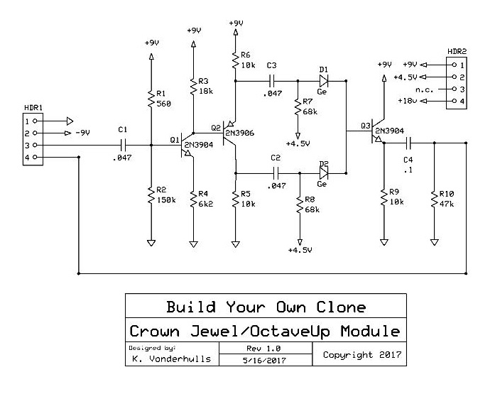
While the octave-up circuit introduces a degree of distortion by virtue of how it functions, it is NOT a fuzz. The octave fuzz pedals, with the Octavia made famous by Hendrix being the best known, combine both fuzz and octave-up circuits into a single pedal. In the octave-up circuit, the function of the diodes is to provide full wave rectification of the guitar signal, not to give signal clipping.

If you take a look at the CJ Octave Up module schematic (below), you'll see that the two diodes are not paired together in opposite polarity as would be the case for signal clipping. They each do half-wave rectification on the guitar signal, which has been split into two equal signals of opposite phase at the 2N3906 transistor before them in the signal path. The half-rectified signals are then recombined into a fully rectified signal which has the octave-up overlayed onto the processed original signal.

Image

_________________
“My favorite programming language is SOLDER” - Bob Pease (RIP)

My Website * My Musical Gear * My DIY Pedals: Pg.1 - Pg.2


Top
 Profile  
 
PostPosted: Tue Aug 25, 2020 11:17 am 
Offline

Joined: Thu Jul 18, 2019 7:51 am
Posts: 111
Hey, thanks for the clarification. I spent much of the day studying up and ordering parts. I saw a video of a green ringer build and it was distorted. Didn't know if that was the pedal or his amp. Thanks again.

Oh, That question originally asked in late July... 2019 and I had no clue what i was doing. I have spent the year building other circuits prototypes. I didn't understand any of that a year ago, and definitely didn't remember the thread. You're awesome as always.


Top
 Profile  
 
PostPosted: Tue Aug 25, 2020 11:30 am 
Offline
Site Admin
User avatar

Joined: Sun Jan 22, 2006 1:39 pm
Posts: 5989
Location: Richland, WA
If you look at the schematic, you'll see that Q1 is literally an LPB boost. R1 should be 560k (typo). It's not configured for a huge amount of gain because of the 6k8 off the emitter, but it's still a boost nonetheless going into Q2. So, it actually is a little bit like a fuzz because you've got a boost cascading into the next transistor.

Q3 is a 1:1 gain emitter follower. It's just a buffer to sum the two signals from Q2.

If you're searching for a clean analog octave up, this would be a good experiment to breadboard: Just flip the order of Q1 and Q3. Put the buffer in front so it doesn't cause Q2 to clip. Put the LPB at the end. Since it's not feeding into anything, you could even change the values of R1 ~ 4 to make it a proper LPB. You'd need to add a volume knob at the end though.

_________________
*patience is a virtue*

Please do not PM me. email is prefered. keith@buildyourownclone.com


Top
 Profile  
 
Display posts from previous:  Sort by  
Post new topic Reply to topic  [ 4 posts ] 

All times are UTC - 6 hours


Who is online

Users browsing this forum: No registered users and 4 guests


You cannot post new topics in this forum
You cannot reply to topics in this forum
You cannot edit your posts in this forum
You cannot delete your posts in this forum
You cannot post attachments in this forum

Search for:
Jump to:  
cron
Powered by phpBB® Forum Software © phpBB Group