Build Your Own Clone Message Board

It is currently Wed Apr 17, 2024 7:11 pm

All times are UTC - 6 hours


Post new topic Reply to topic  [ 127 posts ]  Go to page Previous  1, 2, 3, 4, 5, 6  Next
Author Message
PostPosted: Wed Mar 21, 2012 9:21 pm 
Offline
User avatar

Joined: Tue Dec 28, 2010 6:38 pm
Posts: 1811
Location: Sunny Central Oregon
Quote:
And a little more....

I can help with some of this:

Okay, got some noob questions on the BOM - looking at ordering from Mammoth Elec

1. What are the values for the resistors listed as 1k5, 3k9, 4k7, 5k1, and 560R ? k represents the decimal point so 1k5 is 1.5kohms. R = Ohms so 560R is 560 ohms

2. Which capacitors to get - Nichicon Electrolytic (what voltage?), Xicon Ceramic, or Polyester Film? The pics look like a mix of all three. You will need a mix of at least electrolytic and either ceramic and film. Box caps fit easily in this board. Make sure the Electrolytic are 35v or higher

3. Which diode for Z1 - 1n4742A or 1n4739A?

4. Do TL072CP and MAXX1044CPA work for the IC's specified as TL072 and MAXX1044? For these last two questions search this and the order thread, it is explained.

5. Is there a part to socket the IC's into? You need to buy a socket. Like this one http://www.mammothelectronics.com/620-D ... 0-dip8.htm


Thanks for your help!

Are the TL072CP and MAX1044CPA IC's both 8 pin? No pics on mammoth

Yes, both 8 pins. Look at the board layout and you can see the chip pins. Also go back and read the discussions regarding MAX1044CPA versus the "S"CPA versions. In this order thread. Around page 3 I believe

viewtopic.php?f=15&t=35374&st=0&sk=t&sd=a&start=50

_________________
spin wrote:
A lot on here are using the one handed strippers. They seem to work well, but I just assume use the ol' trusty.


Top
 Profile  
 
PostPosted: Tue Mar 27, 2012 6:55 pm 
Offline
Moderator
User avatar

Joined: Tue Feb 09, 2010 4:45 pm
Posts: 4691
Location: Rochester, NY
All the photos I've seen of these show them built up in large enclosures (a 1590BB I assume). But the PCB seems like it would fit into a 125B with a little planning. Anyone have thoughts on which way to go with this?

_________________
Scott

My band, Austin Hollow


Top
 Profile  
 
PostPosted: Thu Mar 29, 2012 7:19 am 
Offline
Moderator
User avatar

Joined: Tue Feb 09, 2010 4:45 pm
Posts: 4691
Location: Rochester, NY
Getting ready to place my parts order. Maybe I'll get the BB box just to be safe…

_________________
Scott

My band, Austin Hollow


Top
 Profile  
 
PostPosted: Thu Mar 29, 2012 9:12 am 
Offline
User avatar

Joined: Fri Jun 17, 2011 1:54 pm
Posts: 1242
Location: Cleveland, OH
FWIW, with a little filing mine's going in a 1590B so 125B should be no problem. 8)

_________________
tonedeaf wrote:
I'm a sucker for wood.


Top
 Profile  
 
PostPosted: Thu Mar 29, 2012 9:22 am 
Offline
Moderator
User avatar

Joined: Tue Feb 09, 2010 4:45 pm
Posts: 4691
Location: Rochester, NY
saxoftenest wrote:
FWIW, with a little filing mine's going in a 1590B so 125B should be no problem. 8)

I hope you'll take it as a compliment when I say that it's sort of irrelevant to me what size box yours is going into. You ninja you.

_________________
Scott

My band, Austin Hollow


Top
 Profile  
 
PostPosted: Thu Mar 29, 2012 7:49 pm 
Offline
Moderator
User avatar

Joined: Tue Jan 02, 2007 1:24 pm
Posts: 16216
Location: Albany, NY
The Klone V1, in true Centaurian fashion, is configured such that the first stage of the first opamp functions as a buffer which is always in the signal path, whether the main effect circuit is engaged or bypassed. In general, this is fine, but may cause undesirable interactions with other pedals under some circumstances, so I thought I'd look into what would be needed to convert the pedal to a true bypass configuration. Using 
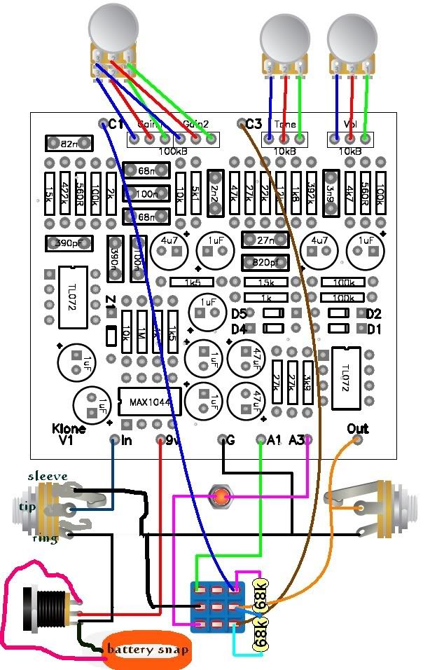
THIS SCHEMATIC that I found at freestompboxes.org, I modified 'Playa's wiring layout diagram for true bypass operation. My layout substitutes the customary 3PDT stompswitch for the DPDT (or 3PDT with one column of lugs unused), and eliminates a handful of components on the PCB (three resistors and an electrolytic cap) as well as the two 68K resistors on the footswitch. You also skip three wire connections to the board (C1, A1 and OUT). The only new addition (besides the 3PDT & its wiring and changing the input jack from a mono to stereo) is a 2.2M resistor between the circuit input and ground. I opted to mount this between lugs 2 and 5 on the footswitch to avoid having to stick it on the board somewhere, but the latter can certainly be done, if you prefer. My Klone V1 true bypass layout diagram is posted below. Also posted is a photo of 'Playa's PCB with the omitted components and wire connections shown in red. Keep in mind that the final component configuration on his PCB is slightly different than the one shown in his & my layout diagrams.

I've had our own dcountry13 look the diagram over, since he's quite familiar with the Klon circuit in several of its forms, and he believes everything looks correct. I bought two of 'Playa's PCBs, and my intention is to build one "stock" and the other as true bypass per this diagram. I will edit this post once I've actually verified it, but in the mean time, if you decide to try it, you do so at your own risk.

UPDATE 3/31/12: I was over at Madbean's site looking at the archived instructions for his discontinued Sunking board and found the directions for converting his v.3 board to true bypass. Lo & behold, Brian says to leave out exactly those same five resistors and one cap, add a pull-down resistor, and leave the analogous eyelets on the PCB unconnected. So while the above modification still isn't verified for the Klone V1 board, it sure is looking awfully good! Thanks, Brian.... :mrgreen:

UPDATE 4/7/12: VERIFIED this date by Grind Customs and Saxoftenest. Thanks, guys!!


Attachments:
Klone_TB_wiring.gif
Klone_TB_wiring.gif [ 99.66 KiB | Viewed 13766 times ]
KloneV1_TB_PCB.JPG
KloneV1_TB_PCB.JPG [ 87.24 KiB | Viewed 13754 times ]

_________________
“My favorite programming language is SOLDER” - Bob Pease (RIP)

My Website * My Musical Gear * My DIY Pedals: Pg.1 - Pg.2
Top
 Profile  
 
PostPosted: Mon Apr 02, 2012 3:32 pm 
Offline
User avatar

Joined: Sat Jun 13, 2009 5:14 pm
Posts: 416
Location: Baltimore, MD
Will bat46 diodes work for D4 an D5?

_________________
BH4RJ


Top
 Profile  
 
PostPosted: Mon Apr 02, 2012 3:37 pm 
Offline
User avatar

Joined: Thu Nov 27, 2008 11:38 am
Posts: 4897
Location: Columbia River Gorge
mafew129 wrote:
Will bat46 diodes work for D4 an D5?


Socket the position and try them. They will make noise, and may sound great, but it is a personal choice.

I really haven't found any diodes that sound HORRIBLE in that position.


_________________
Image

Frag Magnet wrote:


BYOC: So easy even a drunk can do it!
:lol:


Top
 Profile  
 
PostPosted: Mon Apr 02, 2012 4:07 pm 
Offline
User avatar

Joined: Thu Aug 25, 2011 7:24 pm
Posts: 8970
Location: Rouyn-Noranda, Qc
Thanks for the true bypass layout DVM, much appreciated.

Since i don't have my boards in hand, i've started to drill/paint/decal all my enclosures for the klone.

Can someone tell me what is the dimensions of the pcb, so i know if i screwed up?

Thanks

_________________
Comfort Player wrote:
After reflowing and several attempts at signal tracing and switch testing I plugged in the power.


Top
 Profile  
 
PostPosted: Mon Apr 02, 2012 7:43 pm 
Offline
User avatar

Joined: Mon Feb 16, 2009 8:52 am
Posts: 1121
Location: Ferndale, MI
I'm just saying thanks here to gtrplaya101 for doing this... and making sure that this thread stays in my posts section for when I build the thing! Cheers...


Top
 Profile  
 
PostPosted: Mon Apr 02, 2012 8:01 pm 
Offline
Moderator
User avatar

Joined: Tue Jan 02, 2007 1:24 pm
Posts: 16216
Location: Albany, NY
GrindCustoms wrote:
Can someone tell me what is the dimensions of the pcb, so i know if i screwed up?
2 3/8" x 2 1/4"

_________________
“My favorite programming language is SOLDER” - Bob Pease (RIP)

My Website * My Musical Gear * My DIY Pedals: Pg.1 - Pg.2


Top
 Profile  
 
PostPosted: Mon Apr 02, 2012 8:40 pm 
Offline
User avatar

Joined: Thu Aug 25, 2011 7:24 pm
Posts: 8970
Location: Rouyn-Noranda, Qc
duhvoodooman wrote:
GrindCustoms wrote:
Can someone tell me what is the dimensions of the pcb, so i know if i screwed up?
2 3/8" x 2 1/4"


Thanks and it fits perfectly! :mrgreen:

_________________
Comfort Player wrote:
After reflowing and several attempts at signal tracing and switch testing I plugged in the power.


Top
 Profile  
 
PostPosted: Tue Apr 03, 2012 7:17 am 
Offline
User avatar

Joined: Tue Feb 07, 2012 3:18 pm
Posts: 7343
Location: Nashville, TN
srgjbt8 wrote:
I'm just saying thanks here to gtrplaya101 for doing this... and making sure that this thread stays in my posts section for when I build the thing! Cheers...


+1

_________________
powerpopguy wrote:
warm places theory sounds plausible. Occasionally, I wake up and think my snake is missing too, but it turns out it's just a chilly morning. :P


Top
 Profile  
 
PostPosted: Tue Apr 03, 2012 12:41 pm 
Offline
User avatar

Joined: Thu Aug 25, 2011 7:24 pm
Posts: 8970
Location: Rouyn-Noranda, Qc
Just got them Curt! 8)

There's 10 pcb in the picture, the 11th is my stash for my personnal «special one»

So excited! haha! :mrgreen:

Image

_________________
Comfort Player wrote:
After reflowing and several attempts at signal tracing and switch testing I plugged in the power.


Top
 Profile  
 
PostPosted: Tue Apr 03, 2012 4:39 pm 
Offline
User avatar

Joined: Sat Jun 13, 2009 5:14 pm
Posts: 416
Location: Baltimore, MD
GrindCustoms wrote:
Just got them Curt! 8)

There's 10 pcb in the picture, the 11th is my stash for my personnal «special one»

So excited! haha! :mrgreen:


:golf clap:

_________________
BH4RJ


Top
 Profile  
 
PostPosted: Sat Apr 07, 2012 8:48 pm 
Offline
User avatar

Joined: Fri Jun 17, 2011 1:54 pm
Posts: 1242
Location: Cleveland, OH
Thanks DVM for the true bypass option!! You can now mark that VERIFIED. I'd show pics, but I don't want to give away my entry for the build-off just yet... :twisted:

_________________
tonedeaf wrote:
I'm a sucker for wood.


Top
 Profile  
 
PostPosted: Sun Apr 15, 2012 6:20 pm 
Offline
Moderator
User avatar

Joined: Tue Jan 02, 2007 1:24 pm
Posts: 16216
Location: Albany, NY
Third verification on the true bypass wiring, this time my own. Here are two gut shots from my two Klone V1 builds--stock on the left, TB on the right. Note the components left off the board for the TB, the reduced amount of wiring into the PCB, and the 3PDT footswitch with a 2.7M pull-down resistor soldered across lugs 2 and 5:

Image Image

_________________
“My favorite programming language is SOLDER” - Bob Pease (RIP)

My Website * My Musical Gear * My DIY Pedals: Pg.1 - Pg.2


Top
 Profile  
 
PostPosted: Fri Apr 27, 2012 2:57 am 
Offline

Joined: Tue Dec 02, 2008 5:08 pm
Posts: 96
Okay, another silly question: The BOM lists a mono and stereo jack, which is what I bought, but the wiring diagram and duhvoodooman' pic shows using two mono jacks - do I need to get a 2nd mono jack or is there a way to make the stereo jack work? (I notice the TB wiring diagram uses a sterepo jack, but I am doing the buffer build.)


Top
 Profile  
 
PostPosted: Fri Apr 27, 2012 3:11 am 
Offline
User avatar

Joined: Sun Oct 12, 2008 5:18 pm
Posts: 3845
Location: Byron Bay, Australia
You don't have to have two mono jacks, the stereo jack is for the battery users (it's used as a switch so the effect is only powered when a jack is plugged in the input).
Just use the tip and ring connectors on your stereo jack and it will function the same as a mono jack.

_________________
"Spud knows tone"

codtone.com


Top
 Profile  
 
PostPosted: Fri Apr 27, 2012 3:29 am 
Offline

Joined: Tue Dec 02, 2008 5:08 pm
Posts: 96
So when using the stereo jack as the input jack, Tip goes to "In" on the board and Ring goes to AC jack(-), "G" on the board, Ring on the Output jack, and the middle DPDT lug, just as shown on the buffer wiring diagram? And does the battery snap connect to the AC jack as shown on the buffer wiring diagram?


Top
 Profile  
 
PostPosted: Fri Apr 27, 2012 4:08 am 
Offline
User avatar

Joined: Sun Oct 12, 2008 5:18 pm
Posts: 3845
Location: Byron Bay, Australia
So you want to build it buffered and with a battery, right?

First, let me say batteries are Evil :evil: :wink: - also charge pump devices (like this one) tend to consume batteries very quickly too.
That makes them Extra Evil. :twisted:

But, UN-verified, this should work:

Image

Myself, I went true-bypass, no battery... :wink:

_________________
"Spud knows tone"

codtone.com


Top
 Profile  
 
PostPosted: Fri Apr 27, 2012 10:25 am 
Offline

Joined: Tue Dec 02, 2008 5:08 pm
Posts: 96
Awesome - thank you!


Top
 Profile  
 
PostPosted: Sat Apr 28, 2012 7:33 pm 
Offline

Joined: Tue Dec 02, 2008 5:08 pm
Posts: 96
Hopefully LAST question - does A3 connect to long or short leg of LED?


Top
 Profile  
 
PostPosted: Sat Apr 28, 2012 9:08 pm 
Offline
Moderator
User avatar

Joined: Tue Jan 02, 2007 1:24 pm
Posts: 16216
Location: Albany, NY
Long leg.

_________________
“My favorite programming language is SOLDER” - Bob Pease (RIP)

My Website * My Musical Gear * My DIY Pedals: Pg.1 - Pg.2


Top
 Profile  
 
PostPosted: Sun Apr 29, 2012 6:49 am 
Offline
User avatar

Joined: Sat Feb 28, 2009 9:03 am
Posts: 713
Location: Middle of nowhere Va.
So I do not have the BOM here at home and really don't want to do the half hour plus round trip into work to see if I have it on my work computer, so does anyone have the BOM so I know what diode goes where? The link at the start of this thread is down. I can guess by the photos but would rather have the right info.

Thanks.


Top
 Profile  
 
Display posts from previous:  Sort by  
Post new topic Reply to topic  [ 127 posts ]  Go to page Previous  1, 2, 3, 4, 5, 6  Next

All times are UTC - 6 hours


Who is online

Users browsing this forum: No registered users and 3 guests


You cannot post new topics in this forum
You cannot reply to topics in this forum
You cannot edit your posts in this forum
You cannot delete your posts in this forum
You cannot post attachments in this forum

Search for:
Jump to:  
cron
Powered by phpBB® Forum Software © phpBB Group