I was waiting to post this here until all the ducks were in a row ... annnnd PCBs are now in stock at 1776 Effects! http://1776effects.com/store/
My sincere thanks to Josh for thinking highly enough of this to carry it in his line of PCBs. I'm a huge fan of his reverb and delay.
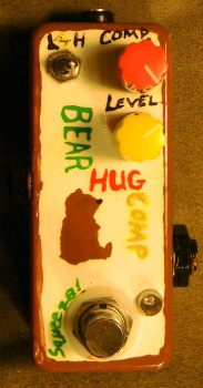
This is one of my design/hacks. The Bearhug is a tonally transparent, ultra-quiet, tiny, and easy-to-build compressor. It occupies some middle ground between the ultra-subtle compressors like the Flatline/Afterlife and Orange Squeezer and the super squishy compressors like the Ross.
Compressors are one of my favorite effects -- I've used an Orange Squeezer as an "always on" pedal in my rig for years now. I've built a lot of different compressors now, and there are a large number of good or great designs out there. I wasn't so much looking to improve on a great design as to find a little bit of unused or underused turf in the DIY community.
I had been talking with Ray Ring (Circuit Salad is his website) recently after building his compressor, which uses an opto-FET, and he mentioned the phrase "linearized FET" as one way to create compression. The use of a linearized FET frees up some interesting design space. It allows anything from a very, very tiny amount of compression to ...well, more attenuation than you'll ever need. And they're faster than an optical design -- the attack can be as little as a few milliseconds. While looking over lots and lots of different compressor schematics, I recognized the use of a linearized FET in the Rothwell Lovesqueeze. I built it and liked it, but wanted to change a few things, such as improving how it reacted to the guitar's volume and the input impedance, and getting better separation between the compression and audio levels.
(I recommend watching in Youtube because the annotations don't show up properly in the embedded version.)
My goals with this design:
1) It had to be easy to build. So no weird resistor values or uncommon capacitors. No difficult to find or unobtainable parts. Pretty much part has a workable substitution even though they're all common. As a side benefit, it's dirt cheap. The entire circuit cost me around $7 including the 9mm pots.
2) No weird biasing or other issues that make it difficult for someone to tell if the effect is working properly. As much as I love Orange Squeezers, if the builder doesn't know what it's supposed to do or sound like, they won't bias it correctly and then it just works as a boost. I wanted to avoid this.
3) It had to be quiet. These days, honestly, if your compressor design hisses and buzzes like a Ross/Dynacomp, it's time to go back to the drawing board. I'm ridiculously happy that I succeeded with this one. This circuit is completely silent -- there's no circuit noise at all, and the high signal-to-noise ratio is identical at all compression settings. (You'll bring up the noise floor when running it as a boost, but it's not contributing any noise -- just amplifying the pickup's hum and your guitar signal with it.)
4) I wanted it small enough to fit in a 1590A. Check!
How it works
The audio path is a MOSFET booster (basically Jack Orman's with a couple adjustments) -- this gave the effect enough output to still work as a boost, but it's super quiet and has extremely high input impedance. There are a few changes to accommodate the diode voltage drop at the 9v input, and I used a negative feedback cap (C4) to cut radio frequencies rather than a cap to ground, but this is all standard stuff.
Tonally, this circuit neither cuts nor boosts any meaningful frequencies. The input and output caps are sufficient for the tonal frequency of at least a 4-string bass (I don't have a 5-string to test on). C4 can be adjusted to add or cut some overall available brightness (I used 47pF in my personal build).
The output volume will be at unity right around noon. The highest setting will be boosted by ~10-15 dB, depending on a handful of tolerances.
There is no tone control in this design, but if you really want one, the best choice is AMZ's version 2 of Mark Hammer's Stupidly Wonderful Tone Control.
The compression path works like this: Your signal is tapped at the collector of Q1, where it is amplified like crazy by a high gain transistor. The comp knob sets the gain within a fairly small range (500R, with a 47R minimum). Your signal is then peak-to-peak rectified (essentially the rectifier circuit from the Lovesqueeze; apparently it's a fairly standard method), and a negative voltage swing of anywhere from about -.2v to -2v is produced at C9, with the size of the swing depending on the size of the signal after it was amplified by Q2. The negative voltage swing then drives up the resistance on the FET (Q3), which at last is connected to the emitter of Q1 through a 47uF cap. The FET's default in this setup is completely on. The resistance of a 2N5457 is only ~300Ohms, so this sets the gain of the Q1 stage a safe distance above the distortion point but still "pretty darned loud." When your input signal drives up the resistance (typically anywhere from about 100 Ohms on the lowest settings to as much as 2K with the highest settings with a really, really hard strum), that lowers the gain of the MOSFET stage, thus decreasing your guitar signal's volume and creating compression. Whew!
C9 is a hold cap, fairly small as hold caps go so that we can get subtle settings. The decay of the cap is set by a parallel resistor; here, we've used a pair in series and a High/Low switch (Sw1) that bypasses the larger resistor, giving us two decay levels. When the switch is on ("Low"), the 10K gives an extremely fast decay -- basically, it will stop compressing immediately after it stops receiving a signal. This makes it work more like peak limiting. When the switch is off ("High"), the added resistance slows down the decay, increasing the total amount of compression available and adding a "duck and swell" effect at the highest settings. 47K is the nominal setting -- the maximum "Low" setting will be about equivalent to the minimum "High" setting -- but 100K may be used for a more dramatic change between Low and High modes.
Credit where credit is due: This circuit design uses some elements from the Lovesqueeze and Jack Orman's (AMZ) Mosfet booster. Mark Hammer and PRR on DIYstompboxes helped me understand the rectifier. Joshua McClarren (Gtr2/1776 Effects) designed the etch and PCB layouts. Extra props to R O Tyree on DIYSB for his help in understanding compressors in general.
I slightly revised this design recently to make it behave better and to get just a little more out of it overall.
Summary of changes: -Change R4 to 4.7K (should bias to ~5V) -Remove R12 -Change R14 to 1K -Use generic silicon diodes for D2 and D3. -Use a 1KC for the comp pot to keep it from bunching up (because R12 was removed) -Optional (for low-output pickups): Change R3 to 4.7K.
Why these changes are good: -More reliable compression with a wider range of pickups -Smoother sound overall. -Slightly more output/boost. -Er ... a few cents cheaper to make!
Okay, I promised Josh a slightly more thorough round of testing and explanation before he adds this to the build doc.
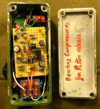
I built a couple boards yesterday to test against my old stock version and did an a/b/c as soon as I got back from work.
Version A - old stock version.
Really only worked when it was just barely turning on. With my single coils, this was pretty much at the top of the compression range. It felt stiff. Also, the total output was less than the other versions here, even with the same perceived amount of compression. I felt like this had only one setting that worked with any given guitar, and that setting was never one that offered anything other than just a touch of compression.
Version B This is on my development board, which has sockets for All The Things -- I set that up as described yesterday with all four mods (and R14 = 100R) to get the maximum squishiness.
This was the opposite. I felt like it was simply TOO easy to trigger. This meant that my minibuckers were sounding best at 0 or 9:00 on the Comp knob. It just felt too rubbery and extreme. Adjusting R3 back down to 2.2K or even lower really didn't back things off quite enough to use it as an almost pure boost. Max compression settings were essentially useless: it would compress even softly played notes down to unity volume, but because the decay is short it sounded like breathing. Ripple also became noticeable with higher output pickups. I can't imagine any pickups being weak enough to need these settings.
Since I had sockets, I tried a few different things and ended up with version C ...
Version C - new version R14: 1K, removed R12, R4 = 4.7K (biases to ~5V), 1N4148 diodes (these could be 1N4001 or whatever).
This works out as a nice compromise. It has a sweet spot with my single coils between 3:00 and max, where it sounds very natural most of the time, and it's able to get above unity volume at any setting. The output is much higher than A overall with the comp backed off but it's still compressing even on the lowest settings with single coils. With humbuckers, it turned on reliably closer to noon but never felt out of control.
The nice thing about doing it this way is that if you WANT the squashed settings, there's room to go upward with minimal changes: increase R3 or even put the Schottky diodes back in.
-------------
Okay, so what's the deal with R14 and why was it 1M in the first version?
I've mentioned that the linearized FET set-up in Bearhug (everything between Q2 and Q3) was lifted wholesale from the Rothwell Lovesqueeze. Apparently, in the Lovesqueeze, the equivalent resistor to R14 is needed because it forms a voltage divider with the equivalent of R8 to split between the audio and control voltage.
In the Bearhug, that's unnecessary. The rectifier is fully decoupled from the audio path and no noise bleeds in. All it's doing is blocking the voltage needed to drive the FET reliably.
--------------- While I'm here ... some mods
-Hey! Anyone want a third "even longer" decay setting? Use a SPDT on-off-on. Wire a 220K to lugs 1 and 3. Replace R10 with a larger resistor, 220K (for a 1s decay). Wire the switch as normal. In the center, R9 and our new R10 are in the circuit all the time = long decay. Flipped so that lugs 1 and 2 are connected, R10 is bypassed (normal short setting). Flipped so that lugs 2 and 3 are connected, a 220K resistor is put in parallel with R10, giving 110K total, for a decay of ~500ms, which is almost the same as our old "long" setting. Is this useful? I dunno. Might be for some people and it's very easy to do!
-I think how I did the emitter on Q2 was unnecessarily complicated. I set it up as if it were another MOSFET driving that stage, but ended up using a BJT because they're cheaper and the transistor characteristics didn't matter much. You could jumper C10 and leave off R13 if you wanted to save a couple parts.
Users browsing this forum: No registered users and 2 guests
You cannot post new topics in this forum You cannot reply to topics in this forum You cannot edit your posts in this forum You cannot delete your posts in this forum You cannot post attachments in this forum