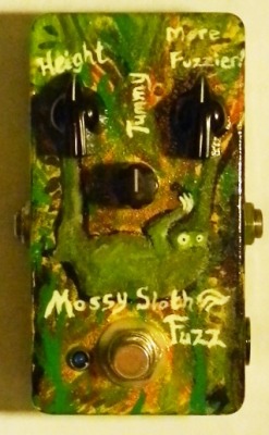
This is my new fuzz/OD hybrid design. Thanks to the forumites on Madbean who voted on the name!
Background/goals:
I've been using a fuzz as my only dirt pedal most of the time for the past couple years. I really like the sound of certain fuzzes when they're pulled back a little, so I started brainstorming ideas for a fuzz that had more OD characteristics. But I also wanted it to be more than just a variation on the fuzz face or some other well-trodden vintage fuzz circuit. So after brainstorming and breadboarding various circuits for a few months, one day on DIYSB, someone posted about emitter diodes to bias a transistor, and Jimi Photon linked to his Tone Blaster. This felt like the missing piece in the puzzle, so I went back to a few different ideas I'd been tossing around, and ended up with this:
Q1 is an input buffer to give us a high input impedance (~2M).
Q1 is a drive stage very similar to the one in the Clipper Ship but with more gain. A volume control works as the gain control for the pedal, and then there's a MOSFET as the "hard" clipper at the end (ultimately based on the Electra Distortion). A MOSFET in this arrangement is an asymmetric clipping diode all on its own. One direction is a silicon body diode -- hard clipping -- while the other side has a very soft knee and works more like soft clipping. It's very efficient. The gain control also has a treble bypass to keep things from getting muddy when it's turned down.
Q3 is the "fuzz" stage, with a couple weird things. There's a MOSFET in the feedback loop similar to the Big Muff for a healthy dose of soft fuzzy clipping, and then the emitter has a MOSFET in place of a biasing resistor (this is the trick I picked up from Jimi Photo's Toneblaster). It's not actually clipping so to speak; it's actually more like an exciter effect. Small signals don't see the bypass; big signals see the bypass and get pushed way up. This makes for super touch sensitive distortion, and it also sounds very tube-y.
There's not a ton of output doing it this way, but in lieu of using a make-up stage I "figured out" (er ... IO plugged things into other things on the breadboard where they don't be long) that I could reference a bypass cap to the 9v supply and get quite a bit of extra gain.
Then there's another MOSFET clipper to ground, a bit of treble cut (R15 and C12), and a level control with a treble bypass like the gain control.
Finally, we reach our output buffer to ensure really low output impedance (a few hundred ohms).
Edit: Is this really that complicated? Like, does it look scary (serious concern since it's meant as a DIY project)? It's the same parts count as a Big Muff Pi.
Now the Spaceman Gemini ... THAT's a candidate for the world's most complicated fuzz ...
I have a friend who takes issue with me calling this thing a fuzz, so I decided to play around with something. This kind of fundamentally changes some things about the pedal, but it will very much make it fuzzy.
Use a Darlington for Q3, and remove its feedback biasing resistor (R12) and replace C8 with a jumper, making this stage similar to the Bazz Fuss I tried sticking with a BC549C, but that actually require more changes and just didn't sound good.
You lose any almost totally clean settings, but with the bass cut way up and the gain way down, it DOES still do a decent mild overdrive and sounds quite good. The other drawback is it adds a little bit of noise when the guitar pot is rolled off some, but nothing intolerable. Finally, output is a little lower, but this thing was already absurdly loud, and it still has a pretty big boost.
Anyway, I just thought I'd put this here for anyone who solders one up and wants more distortion. I might box up one built like this.
So you folks aren't going to believe this, but I apparently designed this effect with the transistors upside down! There's nothing wrong with the stock bill of materials, and the silk screen on the PCB will still be correct if you're using BC549C, but I did fix the schematic to show this.
I also added an alternate bill of materials to the build doc for anyone who wants to flip them around. It does have a touch more gain that way, but the distortion levels aren't too different. It does maybe have a little more clarity.
Only four resistors need to change if you want to go that route. The notes are on page 3 of the build doc.
Just finished the changes. It was really tight getting those transistors out, but wow, what a difference - night and day. Honestly, I'd put this in the 'other circuits' cardboard box, but now I'm going to box it up proper.
I went ahead and updated everything. Schematic and build doc reflect the new values. Note that the silk screen is now correct for "normal" transistors like the 2N5088, and BC549C will be backwards in the PCB. The perf layout is correct for BC549C, and there are no changes to the etch mask.
Users browsing this forum: No registered users and 1 guest
You cannot post new topics in this forum You cannot reply to topics in this forum You cannot edit your posts in this forum You cannot delete your posts in this forum You cannot post attachments in this forum