Build Your Own Clone Message Board

It is currently Tue Apr 16, 2024 1:07 pm

All times are UTC - 6 hours


Post new topic Reply to topic  [ 11 posts ] 
Author Message
PostPosted: Sat Jul 07, 2018 2:37 am 
Offline

Joined: Tue Nov 10, 2015 2:04 am
Posts: 13
Hello,

Thanks all for your help with previous projects. With your feedback I've gotten better at build technique and generally have been able to deal with most problems with better soldering and basic troubleshooting. I am currently working on a green pony build with a specific problem however that has me stumped.

Pedal works 99% fine (sounds great!). Powers up obviously, and has both bypass and through sound. All pots work, and the tone switch works beautifully. The one thing that doesn't appear to be working is the clipping switch. Basically it gives me no differences in tone in any position. No audible noise when switching, no perceptible change to the sound of the guitar at any position regardless of where I have gain, volume, or tone knobs. I am playing a tele through an ac15, and have a good ear for tone, and I'm confident the switch is doing nothing.

Opening the pedal up I find that I get the correct directional connectivity on both sides of the of the on-off-on switch, so the switch itself seems to be doing its job. I have also checked connectivity from the switch back to the gain pot, and all appears to be sound. I have attached a diagram of the connections I have tested (connectivity in blue, voltage in green). As well as images of the front and back of the area. This is the extent of my troubleshooting prowess however. Could use some ideas on what connections I should be focusing on for this specific set of symptoms. The only thought I have is that the entire gain circuit is out, and I'm not sure how to test this or fix it as this starts to enter IC territory, which I'm less comfortable querying.

That said, pedal sounds great otherwise, in what I assume is normal mode sans C3. The diode switcher is a bonus but frankly I was just bothered enough after going through all the connections that I felt it worth a check with the board for advice.

Much appreciate any help or ideas.

Attachment:
GP diagram1.jpg
GP diagram1.jpg [ 120.17 KiB | Viewed 5004 times ]

Attachment:
IMG_2119a.jpg
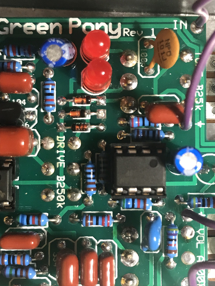
IMG_2119a.jpg [ 439.05 KiB | Viewed 5004 times ]

Attachment:
IMG_2121a.jpg
IMG_2121a.jpg [ 443.23 KiB | Viewed 5004 times ]


Top
 Profile  
 
PostPosted: Sat Jul 07, 2018 9:39 am 
Offline
Moderator
User avatar

Joined: Tue Jan 02, 2007 1:24 pm
Posts: 16216
Location: Albany, NY
Could you please post a photo of the entire component side of the PCB?

_________________
“My favorite programming language is SOLDER” - Bob Pease (RIP)

My Website * My Musical Gear * My DIY Pedals: Pg.1 - Pg.2


Top
 Profile  
 
PostPosted: Fri Jul 13, 2018 1:09 am 
Offline

Joined: Tue Nov 10, 2015 2:04 am
Posts: 13
duhvoodooman wrote:
Could you please post a photo of the entire component side of the PCB?


Here you go. Tried my best to get everything in a single shot, but no doubt some areas are obscured. If there's a particular portion of interest, I can re-take.

Attachment:
IMG_2142a.jpg
IMG_2142a.jpg [ 369.72 KiB | Viewed 4947 times ]


Top
 Profile  
 
PostPosted: Fri Jul 13, 2018 12:28 pm 
Offline
Site Admin
User avatar

Joined: Sun Jan 22, 2006 1:39 pm
Posts: 5989
Location: Richland, WA
So the blue lines represent continuity?

If so, there is something wrong at the switch. If you flip the bat one direction, the center pin should have continuity with the pin in the opposite direction. And if you have it in the middle, the middle pin shouldn't have continuity with either outer pin. Perhaps there's a short inside the switch, or maybe you have a small strand of bare wire or a solder bridge under the switch that you can't see that's causing a short.

_________________
*patience is a virtue*

Please do not PM me. email is prefered. keith@buildyourownclone.com


Top
 Profile  
 
PostPosted: Sun Jul 15, 2018 12:53 pm 
Offline

Joined: Tue Nov 10, 2015 2:04 am
Posts: 13
byoc wrote:
So the blue lines represent continuity?

If so, there is something wrong at the switch. If you flip the bat one direction, the center pin should have continuity with the pin in the opposite direction. And if you have it in the middle, the middle pin shouldn't have continuity with either outer pin. Perhaps there's a short inside the switch, or maybe you have a small strand of bare wire or a solder bridge under the switch that you can't see that's causing a short.


Correct, when I flip the switch left, the pins have continuity in the opposite direction and no continuity in the same direction. And vice versa. I just didn't have a good way to draw that on the picture without making it confusing. Switch itself seems to be working correctly by my understanding of it.


Top
 Profile  
 
PostPosted: Sun Jul 15, 2018 3:17 pm 
Offline
Moderator
User avatar

Joined: Tue Jan 02, 2007 1:24 pm
Posts: 16216
Location: Albany, NY
electrocompetent wrote:
Correct, when I flip the switch left, the pins have continuity in the opposite direction and no continuity in the same direction. And vice versa. I just didn't have a good way to draw that on the picture without making it confusing. Switch itself seems to be working correctly by my understanding of it.

Yes, that's correct operation. For all of these mini-toggles, the connection is made between the center lug/pin and the outside lug/pin on the side opposite the one that the toggle bat is switched to.

_________________
“My favorite programming language is SOLDER” - Bob Pease (RIP)

My Website * My Musical Gear * My DIY Pedals: Pg.1 - Pg.2


Top
 Profile  
 
PostPosted: Mon Jul 16, 2018 11:23 pm 
Offline

Joined: Tue Nov 10, 2015 2:04 am
Posts: 13
duhvoodooman wrote:
electrocompetent wrote:
Correct, when I flip the switch left, the pins have continuity in the opposite direction and no continuity in the same direction. And vice versa. I just didn't have a good way to draw that on the picture without making it confusing. Switch itself seems to be working correctly by my understanding of it.

Yes, that's correct operation. For all of these mini-toggles, the connection is made between the center lug/pin and the outside lug/pin on the side opposite the one that the toggle bat is switched to.


So the switch works, and everything seems to connect back to the IC. But the switch just doesn't do anything. Any ideas what it might be or how to diagnose?


Top
 Profile  
 
PostPosted: Tue Jul 17, 2018 9:02 am 
Offline
Moderator
User avatar

Joined: Tue Jan 02, 2007 1:24 pm
Posts: 16216
Location: Albany, NY
Does the drive pot work, i.e. add more & more distortion and sustain to your output signal as it's turned CW?

The clipping section of the circuit is located in the feedback loop of IC1, along with the drive (gain) control and the tone switch, and connecting to the op amp at pins 1 & 2. See schematic below. Since your tone switch works, that section of the feedback circuit to the left of the diagram must be functional, and the op amp pin connections must be OK. This leads me to wonder if the drive pot is doing anything. If there's no gain being added to your dry signal, then you probably wouldn't get any clipping because the signal isn't strong enough to exceed the forward voltage threshold of the diodes.

Also, I'd suggest that you check to make sure that the back of that dual-gang drive pot isn't contacting the solder joints beneath it, which could short the feedback signal. You might want to insert a thick piece of paper, such as a business card, between the back of the pot and the PCB.

Image

_________________
“My favorite programming language is SOLDER” - Bob Pease (RIP)

My Website * My Musical Gear * My DIY Pedals: Pg.1 - Pg.2


Top
 Profile  
 
PostPosted: Thu Jul 19, 2018 2:31 am 
Offline

Joined: Tue Nov 10, 2015 2:04 am
Posts: 13
duhvoodooman wrote:
Does the drive pot work, i.e. add more & more distortion and sustain to your output signal as it's turned CW?

The clipping section of the circuit is located in the feedback loop of IC1, along with the drive (gain) control and the tone switch, and connecting to the op amp at pins 1 & 2. See schematic below. Since your tone switch works, that section of the feedback circuit to the left of the diagram must be functional, and the op amp pin connections must be OK. This leads me to wonder if the drive pot is doing anything. If there's no gain being added to your dry signal, then you probably wouldn't get any clipping because the signal isn't strong enough to exceed the forward voltage threshold of the diodes.

Also, I'd suggest that you check to make sure that the back of that dual-gang drive pot isn't contacting the solder joints beneath it, which could short the feedback signal. You might want to insert a thick piece of paper, such as a business card, between the back of the pot and the PCB.

Image


Thanks for the suggestions. The drive pot does work, and adds beautiful distortion. I did check to see if there might be contact from the pot. There's ample clearance and I can't even push the pot down to make it touch the PCB without putting a lot of force on it (which I'm not going to do). I will go ahead and put some paper there, but I don't think that's the problem.

So I've ruled out the switch itself. It's unlikely that it's a faulty diode because both diode circuits seem to not work. The tone switch works, so it has to be on the front side of the switch, but I've checked connectivity from the switch all the way back to upper section of the drive pot.

Could the drive pot itself be partially faulty in a way that the gain section would work but the clipping section was not engaged?


Top
 Profile  
 
PostPosted: Tue Jul 24, 2018 10:57 am 
Offline
Site Admin
User avatar

Joined: Sun Jan 22, 2006 1:39 pm
Posts: 5989
Location: Richland, WA
From your continuity chart, I don't see any connection to the anode of D4.

_________________
*patience is a virtue*

Please do not PM me. email is prefered. keith@buildyourownclone.com


Top
 Profile  
 
PostPosted: Thu Jul 26, 2018 4:27 pm 
Offline

Joined: Tue Nov 10, 2015 2:04 am
Posts: 13
byoc wrote:
From your continuity chart, I don't see any connection to the anode of D4.


Thanks, I'll check once I get back from travels.


Top
 Profile  
 
Display posts from previous:  Sort by  
Post new topic Reply to topic  [ 11 posts ] 

All times are UTC - 6 hours


Who is online

Users browsing this forum: No registered users and 2 guests


You cannot post new topics in this forum
You cannot reply to topics in this forum
You cannot edit your posts in this forum
You cannot delete your posts in this forum
You cannot post attachments in this forum

Search for:
Jump to:  
Powered by phpBB® Forum Software © phpBB Group