Attachment:
 IMG_1470_comp.jpg [ 289.51 KiB | Viewed 4624 times ]
The foot switches on my Crown Jewel are seemingly doing nothing. The LED's don't light up and the pedal isn not working. I originally had the wrong relays in it when I first tried to test it. I had the TQ2-L-5V single coil latching relays in there, cause that's what I use on my finish line relay boards. I suspected that was the issue, so I put in some other orange colored NEC 551-EA2-5SNJ relays I had, and strangely enough, the LED's didn't light up but something was happening with the pedal. I could turn the knobs and get some distortion and the switches had an affect on it. It's almost like the pedal was working, but still the LED's were off and it it definitely didn't sound good like it's suppose to. I ordered my momentary switches and most of my parts from BYOC, but I was wondering about whether it's possible to have the wrong momentary foot switches. You know, the whole "NO" "NC" thing. My relay boards take TQ2-L-5V single coil latching relays and use Normally open momentary foot switches. So, is it possible the TQ2-5V non-latching relays need a different foot switch such as Normally Closed momentary?
I realized that they were supposed to be TQ2-5V non-latching relays and purchased and installed those, but nothing is still happening. I don't know if it's possible that I blew some parts in trying to use the wrong relays first, but I've changed almost all the chips and transistors out for new ones, and still nothing.
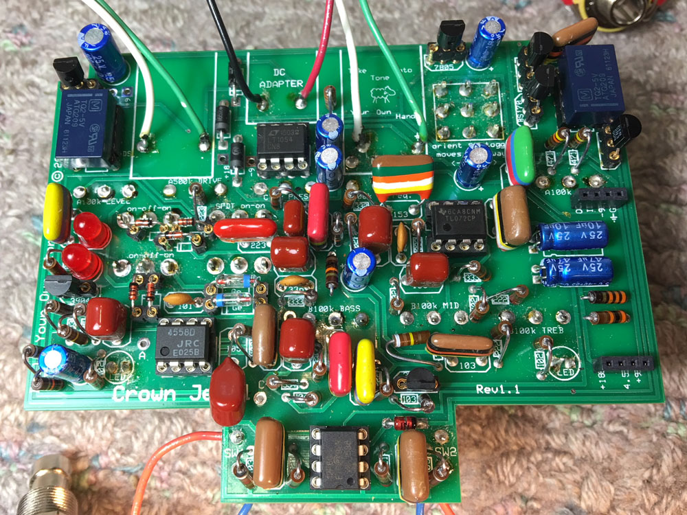
Another thing, is that one of the D9D diodes broke in half when I was beginning to socket them, so I had to just use the only other germanium transistors I had, which I don't know exactly what they are. The clear with blue stripes in my picts. So, I suspected that could be the issue and started trying to take DC voltage readings around the pedal to see if the voltage suddenly dropped out anywhere. IDK what I'm doing very much with the multimeter troubleshooting, but it was strange that around the bottom left of the board, there seemed to be no voltage. No voltage to either side of the germanium transistors. Can someone suggest other germanium transistors to try until the new D9D's I ordered arrive?
I saw in a post to measure the microprocessor legs and to see if leg one was getting 5V, and it was. Then it said that leg 2 should be getting 5V after you push the foot switch, but there was no voltage there. So, leading me back to thinking it's my switching or relays. Plus, the pedal was sort of working with the NEC 551-EA2-5SNJ relays, so I wasn't thinking it could be the germanium diodes as my real problem.
Sorry for the giant explanation, but just trying not to miss anything that could be important. The soldering in my picts looks dirty, cause I went through all of them with a probe and scraped away the melted plastic around them to make sure there were no bridges happening anywhere. There were none. The few places where two solder joints were joined, I made sure that they were suppose to be joined anyways, such as two diodes that are in series. I've thoroughly examined everything and there are no parts accidentally touching each other. I have the plastic dust caps on the pots, so they're not a problem. All my solder connections seem to be solid. I've been making pedals for some 15 years now with a high success rate. I think I've only found one bad solder connection once in my career with some 50-100 pedals made. I read all of the other posts on here with Crown Jewel problems and I don't believe I have any of the same problems. All of my switches are oriented correctly. Same with all of my parts that require orientation. The LEDs, diodes, electrolytic caps, IC's, and relays are all correctly oriented.
Anyways, I'm getting to be stumped and could use some advice on measuring places with my multimeter to help diagnose the problem. Here are some picts I took, but I'm not sure they'll help at all since my parts all seem to be installed correctly, and the fact that I use bigger tropical fish caps and AB resistors.
Oh, forgot to mention that I measure every part I can measure with my multimeter and scrape the leads clean of oxidation and what not before soldering. So, all my resistors and caps are measured, then immediately cleaned, and then I insert them into the board directly after that. Then, I bend the leads so they stay in place in the board. The likely hood of me installing a bad or incorrect valued cap or resistor is about none. Never done it before.


