Build Your Own Clone Message Board

It is currently Thu May 02, 2024 2:19 am

All times are UTC - 6 hours


Post new topic Reply to topic  [ 7 posts ] 
Author Message
PostPosted: Sat Apr 02, 2022 5:17 pm 
Offline

Joined: Thu Dec 16, 2021 8:20 pm
Posts: 64
Hi,
I finished up the orange distortion the other day. Had issues including no led.

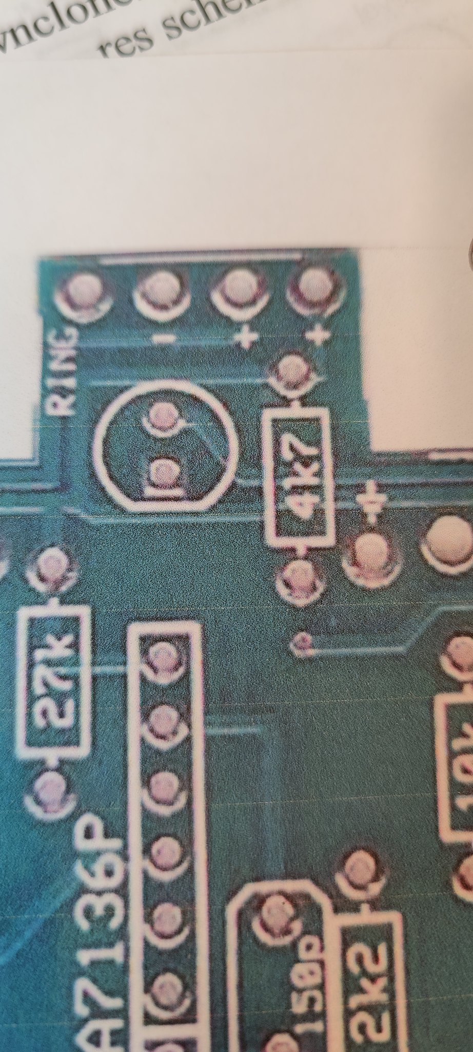
After a bit of forum digging I noticed the pads on my orange distortion 1.1 are reversed to the orange distortion 1.0 pads.

Round and square pads are opposites. Is this an error in the pcb? And my led is backward? Or is this why there is a 1.1?

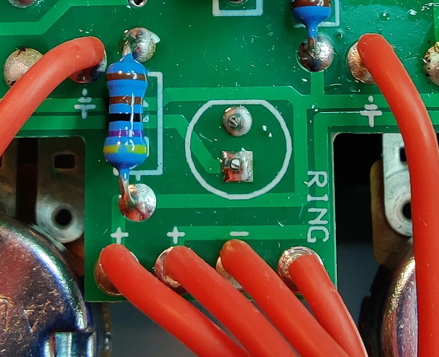
My led is installed flat side like the image. Positive long lead in the square pcb pad. Correct to the 1.1 pcb.

Am I wrong in thinking the positive current is coming from DC jack through 4k7 resistor into the round pad on led pcb 1.1 meaning my led is backwards. Because current should be to the positive lead of the led?

Flat side of led is negative. Which is short lead.

Looking at the 1.0 pcb showing flat side positive. Makes me think the 1.0 pads or image are wrong or... My 1.1 is wrong...

*** Update***
I swapped the led positive to round pad negative flat side to square pad and led works correctly when switched.

Thanks.

Image

Image


Top
 Profile  
 
PostPosted: Sat Apr 02, 2022 9:06 pm 
Offline
Moderator
User avatar

Joined: Tue Jan 02, 2007 1:24 pm
Posts: 16233
Location: Albany, NY
From page 10 of the instructions:

"The LED will have one lead that is longer than the other. The longer lead goes in the hole of the square solder pad."

_________________
“My favorite programming language is SOLDER” - Bob Pease (RIP)

My Website * My Musical Gear * My DIY Pedals: Pg.1 - Pg.2


Top
 Profile  
 
PostPosted: Sun Apr 03, 2022 9:19 am 
Offline

Joined: Thu Dec 16, 2021 8:20 pm
Posts: 64
Yes, I know this according to the instructions. *The second image is from the instructions.*

My question is, if you look at the pictures. Sorry one is upside down to the other.

Are the pads in version 1.1 correct?

Look at the square and round holes in both pictures. The paper picture is from the instructions.

If you look at 1.1 pcb, the round negative hole pad is connected to the 4k7 resistor, which is then connected to DC input. Should this resistor connect to the positive lead on the led?

I am a noob just trying to understand the dynamics of the current path. So I very well could be confused. :)

Thanks


Top
 Profile  
 
PostPosted: Sun Apr 03, 2022 10:59 am 
Offline
Moderator
User avatar

Joined: Tue Jan 02, 2007 1:24 pm
Posts: 16233
Location: Albany, NY
Yeah, sure looks like the LED pads are reversed on this current version of the PCB. Hmm, wonder why we haven't see a rash of people reporting that on this kit??

Actually, it doesn't matter if the 4K7 resistor is between the P/S and the LED or between the LED and ground. Its function is to limit the amount of current flowing through the LED so that it doesn't burn out, hence the designation "CLR" (current limiting resistor). It will do this in either position, though it's usually placed before the LED.

_________________
“My favorite programming language is SOLDER” - Bob Pease (RIP)

My Website * My Musical Gear * My DIY Pedals: Pg.1 - Pg.2


Top
 Profile  
 
PostPosted: Sun Apr 03, 2022 12:05 pm 
Offline

Joined: Thu Dec 16, 2021 8:20 pm
Posts: 64
Quote:
Actually, it doesn't matter if the 4K7 resistor is between the P/S and the LED or between the LED and ground.


But in this case it does matter if the positive lead of the LED is connected to the 4k7 which is connected to power? Because the positive LED lead needs to be connected to power? Because the led only allows current in one direction? Is this a correct assumption?


Top
 Profile  
 
PostPosted: Sun Apr 03, 2022 12:16 pm 
Offline
Moderator
User avatar

Joined: Tue Jan 02, 2007 1:24 pm
Posts: 16233
Location: Albany, NY
Yes, that is so.

_________________
“My favorite programming language is SOLDER” - Bob Pease (RIP)

My Website * My Musical Gear * My DIY Pedals: Pg.1 - Pg.2


Top
 Profile  
 
PostPosted: Sun Apr 03, 2022 12:21 pm 
Offline

Joined: Thu Dec 16, 2021 8:20 pm
Posts: 64
Thanks! It's working! (my brain not the pedal :)


Top
 Profile  
 
Display posts from previous:  Sort by  
Post new topic Reply to topic  [ 7 posts ] 

All times are UTC - 6 hours


Who is online

Users browsing this forum: No registered users and 5 guests


You cannot post new topics in this forum
You cannot reply to topics in this forum
You cannot edit your posts in this forum
You cannot delete your posts in this forum
You cannot post attachments in this forum

Search for:
Jump to:  
Powered by phpBB® Forum Software © phpBB Group