Build Your Own Clone Message Board

It is currently Fri Apr 19, 2024 4:52 pm

All times are UTC - 6 hours


Post new topic Reply to topic  [ 6 posts ] 
Author Message
PostPosted: Mon Nov 07, 2022 10:46 am 
Offline

Joined: Mon Nov 07, 2022 10:32 am
Posts: 4
I spent a good bit of the weekend wiring up the Mouse kit I got. When turned off, I get clean signal through to the amplifier. When turned on, silence but the LED does turn on. I saw someone else had this issue and the advice was redo all the soldering but I've included photos in case anyone sees something specific or has ideas about more targeted strategies for trouble shooting. Can I us the DMM to just check continuity across the various components? Any help/ advice is appreciated.

https://photos.app.goo.gl/qKLSWYXwZrj1mi9C7
https://photos.app.goo.gl/xVwSWRpaGrE7WdLp6
https://photos.app.goo.gl/sZDApppCT16VXYhs7
https://photos.app.goo.gl/TUqtq3mnLbUtHu1v9


Top
 Profile  
 
PostPosted: Mon Nov 07, 2022 12:18 pm 
Offline
Moderator
User avatar

Joined: Tue Jan 02, 2007 1:24 pm
Posts: 16222
Location: Albany, NY
OK, a few comments and suggestions:

  1. Nothing appears to be out of place, so good on you there, except...
  2. ...the clipping LED's are mounted crosswise, so that middle setting of the toggle switch won't provide any signal clipping. Refer to the photo on page 4 of the instructions for their proper mounting orientation. This minor error is unrelated to your stated problem, but should be corrected to enable that clipping option.
  3. A photo of the solder side of the board with the wiring all connected to the PCB would be useful. The only desoldering you need to do to get the "guts" out of the enclosure is the three wire connections at the DC jack--other than that, it's just a matter of removing nuts & washers. Once removed, I'd inspect all the solder joints for possible bridging/shorting to the adjacent joints and wire connections and trim off protruding component leads and wire ends to minimize the possibility of shorting. Also check to insure that you don't have contact between the backs of the two lower pots and the solder joints beneath them. If needed, insulate the backs of those pots with electrical tape (not needed if the pots have plastic dust covers, as some do). You can gently bend the legs of the pots to get underneath them, then bend back when done.
  4. I'd clean up the protruding wire ends on the footswitch. Probably not a factor here, but that's good practice for avoiding signal shorts.
  5. Wiring on the two I/O jacks is much longer than it needs to be. Again, doesn't appear to be a factor here but something to keep in mind for the future. That photo in the instructions is what to shoot for.
  6. Re: using your DMM--yes, but not for continuity. The first thing I'd check would be DC voltage levels on the pins of the IC and the legs of the JFET, and report them here. Here's how to do that:

    Set your multimeter to the DC voltage mode, indicated by a solid line above a dotted one. Use the 20VDC range setting if it's not an auto-ranging meter. Your power source needs to be connected and there needs to be a cable in the input jack. If the pedal is assembled into the metal enclosure, put the black probe into one of the corner screw bosses of the enclosure--this is your ground connection. If the "guts" are out of the enclosure, use the sleeve tab of the input jack for the ground connection. Then touch the red probe to each point that you want to measure. See image below for the numbering of the IC pins.

    Image

_________________
“My favorite programming language is SOLDER” - Bob Pease (RIP)

My Website * My Musical Gear * My DIY Pedals: Pg.1 - Pg.2


Top
 Profile  
 
PostPosted: Wed Nov 09, 2022 11:30 am 
Offline

Joined: Mon Nov 07, 2022 10:32 am
Posts: 4
Thank you for all the pointers. I've been meaning to follow up but just got behind the last few days. I'm going to spend some time with this tomorrow and will report back about what I find. Again, thank you.


Top
 Profile  
 
PostPosted: Thu Nov 10, 2022 8:43 pm 
Offline

Joined: Mon Nov 07, 2022 10:32 am
Posts: 4
Status Update:

I removed the old LED's. Boy was that a bit more of a hassle than I expected but they're off. I ended up destroying the leads on them in the process so I replaced them with a pair of LED's that I had from the physics lab I took in college. One of them is green which I'm guessing might have some impact on the frequency range handled there but I'm hoping it still works.

The pots didn't seem to be touching the back but I still put some electrical tape across them for good measure.

That out of the way. It is now acting very temperamentally. I took desoldered DC jack and took the rest of the guts out of the enclosure. When I hooked a 9V battery and a guitar cable up to try and turn it on and start testing the IC, the power started going in and out and seemed to be doing so at first in response to the input and output jacks being moved or fussed with. At first, I was able to move one or the other and get it to stay turned on. This stopped working after I tested the third spot on the IC. Below are more photos and the voltage readings for the first three spots on the IC. I have to believe that something is touching something it shouldn't and that it's causing the whole thing to short out but I don't see it and can't figure it out.
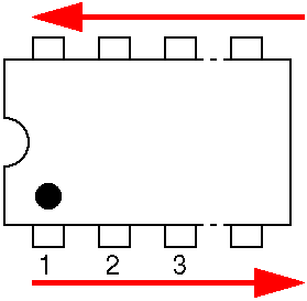
IC:
1 = 7.51V
2 = 4.13V
3 = 2.02V

https://photos.app.goo.gl/4QvwUKW1pJBEbM1H6
https://photos.app.goo.gl/TU6oH9VeWRg9uxvb8
https://photos.app.goo.gl/f6JETszK57pEcAMQA
https://photos.app.goo.gl/mHkeZpVbsHSHTz5v8

Please let me know if other photos or info would be helpful. Thank you!


Top
 Profile  
 
PostPosted: Fri Nov 11, 2022 7:26 pm 
Offline

Joined: Mon Nov 07, 2022 10:32 am
Posts: 4
It works! I think there were a few things going on. One, I had the DC jack rotated 90 degrees so all the wires run to it where in the wrong place, I'm not even sure why the LED turned on when I had a battery in it. I also added some electrical tape to the pots and turned the LED's. This is honestly my favorite distortion pedal. Thanks!


Top
 Profile  
 
PostPosted: Fri Nov 11, 2022 7:50 pm 
Offline
Moderator
User avatar

Joined: Tue Jan 02, 2007 1:24 pm
Posts: 16222
Location: Albany, NY
Glad to hear that you got it sorted out! ENJOY!!! :mrgreen:

_________________
“My favorite programming language is SOLDER” - Bob Pease (RIP)

My Website * My Musical Gear * My DIY Pedals: Pg.1 - Pg.2


Top
 Profile  
 
Display posts from previous:  Sort by  
Post new topic Reply to topic  [ 6 posts ] 

All times are UTC - 6 hours


Who is online

Users browsing this forum: No registered users and 5 guests


You cannot post new topics in this forum
You cannot reply to topics in this forum
You cannot edit your posts in this forum
You cannot delete your posts in this forum
You cannot post attachments in this forum

Search for:
Jump to:  
cron
Powered by phpBB® Forum Software © phpBB Group