Build Your Own Clone Message Board

It is currently Wed May 01, 2024 6:00 pm

All times are UTC - 6 hours


Post new topic Reply to topic  [ 39 posts ]  Go to page 1, 2  Next
Author Message
PostPosted: Tue Apr 25, 2023 7:56 pm 
Offline

Joined: Wed Aug 10, 2022 11:17 pm
Posts: 28
So, I’m sure I’ve made a mistake

I have continuity from input to output

I have power in correct voltage

The LED doesn’t light up

No sound coming out


Attachments:
File comment: Where did I go wrong?
84CB96C0-5BCC-46E3-929B-3D1846C5FE73.jpeg
84CB96C0-5BCC-46E3-929B-3D1846C5FE73.jpeg [ 384.43 KiB | Viewed 2021 times ]
Top
 Profile  
 
PostPosted: Tue Apr 25, 2023 8:06 pm 
Offline
Moderator
User avatar

Joined: Tue Jan 02, 2007 1:24 pm
Posts: 16232
Location: Albany, NY
Warder wrote:
No sound coming out

Whether bypassed or engaged?

_________________
“My favorite programming language is SOLDER” - Bob Pease (RIP)

My Website * My Musical Gear * My DIY Pedals: Pg.1 - Pg.2


Top
 Profile  
 
PostPosted: Wed Apr 26, 2023 12:30 am 
Offline

Joined: Wed Aug 10, 2022 11:17 pm
Posts: 28
Correct, doesn’t matter if it’s bypassed or engaged, nothing. I’ve reflowed the solder joints, double checked my component values, replaced some wire, double checked to make sure power is getting in. I’m showing 9.29VDC across the hot and neutral of the power input. I built an audio probe today, so I guess that is the next step, though if I have continuity all the way through, I’m not sure what’s going on there.


Top
 Profile  
 
PostPosted: Wed Apr 26, 2023 9:22 am 
Offline
Moderator
User avatar

Joined: Tue Jan 02, 2007 1:24 pm
Posts: 16232
Location: Albany, NY
Check lug 4 of the footswitch for continuity to ground.

_________________
“My favorite programming language is SOLDER” - Bob Pease (RIP)

My Website * My Musical Gear * My DIY Pedals: Pg.1 - Pg.2


Top
 Profile  
 
PostPosted: Wed Apr 26, 2023 10:25 am 
Offline
Site Admin
User avatar

Joined: Sun Jan 22, 2006 1:39 pm
Posts: 5991
Location: Richland, WA
A clear pic of your wiring would be a big help as well.

_________________
*patience is a virtue*

Please do not PM me. email is prefered. keith@buildyourownclone.com


Top
 Profile  
 
PostPosted: Wed Apr 26, 2023 11:18 am 
Offline
Moderator
User avatar

Joined: Tue Jan 02, 2007 1:24 pm
Posts: 16232
Location: Albany, NY
Warder wrote:
...though if I have continuity all the way through, I’m not sure what’s going on there.

Please clarify this statement. Are you saying that you have continuity from the tip of the input jack to the tip of the output jack when in bypassed mode? It's important that we know (1) the two points where you placed your meter probes for this continuity test, and (2) what the position of the footswitch was.

_________________
“My favorite programming language is SOLDER” - Bob Pease (RIP)

My Website * My Musical Gear * My DIY Pedals: Pg.1 - Pg.2


Top
 Profile  
 
PostPosted: Thu Apr 27, 2023 7:47 am 
Offline

Joined: Wed Aug 10, 2022 11:17 pm
Posts: 28
Please forgive my lack of clarity.

When switch is in bypass there is no continuity from tip of input to tip of output. When engaged there is continuity from tip of input to tip of output (both jacks in this case).

I’m connecting wiring pictures. I was trying to change the layout and so used leads to connect instead of board mounting the switches and pots. Also been having problems because of how I positioned the LED, I’m pulling it off the board, and will connect using hookup wire and insulate with heat shrink.


Attachments:
0AB5FA45-EEB6-4152-8235-EEE69C6E7F29.jpeg
0AB5FA45-EEB6-4152-8235-EEE69C6E7F29.jpeg [ 93.66 KiB | Viewed 1983 times ]
File comment: Wiring
E5CB57E5-7212-4A50-808C-AC1E90DC915F.jpeg
E5CB57E5-7212-4A50-808C-AC1E90DC915F.jpeg [ 164.48 KiB | Viewed 1983 times ]
Top
 Profile  
 
PostPosted: Thu Apr 27, 2023 9:37 am 
Offline

Joined: Mon Nov 23, 2020 1:39 pm
Posts: 183
Location: Vermont
Quote:
When switch is in bypass there is no continuity from tip of input to tip of output. When engaged there is continuity from tip of input to tip of output (both jacks in this case).


This sounds like the opposite of what it should be, but that could turn simply on an understanding of what bypass means.

In "bypass" mode the signal presented at the input jack is routed directly to the output jack, bypassing the internal circuitry. There should be electrical connectivity (continuity) between the tip lugs of the two 1/4-inch jacks.

In non-"bypass" mode the signal from the input jack must pass through the internal circuitry in order to arrive at the output jack. In this case it is extremely unlikely that the continuity check function of a multimeter would show continuity between the tip lugs of the two 1/4-inch jacks.

If there is some additional issue causing the LED not to illuminate, it is difficult (impossible?) to know, just by looking, whether the footswitch setting is putting the pedal in bypass mode or not. But in this case you can find out by exploring the connectivity between the footswitch lugs themselves, via the continuity function of your multimeter. Lugs 2, 5, and 8 always connect somewhere. In bypass mode, they connect respectively to lugs 3, 6, and 9. In "effect switched in" mode they instead connect to lugs 1, 4, and 7. You can use this to determine the state of the footswitch.


Top
 Profile  
 
PostPosted: Thu Apr 27, 2023 9:44 am 
Offline

Joined: Wed Aug 10, 2022 11:17 pm
Posts: 28
I’ll double check, but yes, I misunderstood the specific meaning of bypass. I’ll look into the lugs. I rewired the LED and discovered a burned trace from the LED to the CLR, which I have now soldered a jumper to connect. So now I’ll try again


Top
 Profile  
 
PostPosted: Thu Apr 27, 2023 10:06 am 
Offline
Moderator
User avatar

Joined: Tue Jan 02, 2007 1:24 pm
Posts: 16232
Location: Albany, NY
Warder wrote:
When switch is in bypass there is no continuity from tip of input to tip of output. When engaged there is continuity from tip of input to tip of output (both jacks in this case).

I would suggest from this description that you are confusing the two footswitch positions. You should have tip-to-tip continuity in BYPASS mode, and not when engaged. Since your LED isn't lighting to distinguish between the two, this mix-up is easy to understand. Once engaged, continuity is lost as soon as the first significant source of resistance is encountered in the signal path....which is the 10 Kohm R1 resistor at the very start of the effect circuit on the PCB.

So assuming that you have the expected bypassed signal path continuity and still aren't getting anything at the output, this strongly suggests that the signal is shorting to ground somewhere in it's journey. Have you checked for continuity between lug 4 of the footswitch and ground, as I previously suggested? Please check this with the switch in the bypass position.

Re: no LED light-up, please take the following measurements with power connected and a cable in the input jack:

  • DC voltage level at the lower/square solder pad of the LED connection on the PCB
  • Continuity between the SLEEVE tab of the input jack and the sleeve of the instrument cable plugged into it
  • Continuity between the RING tab of the input jack and the sleeve of the instrument cable plugged into it

_________________
“My favorite programming language is SOLDER” - Bob Pease (RIP)

My Website * My Musical Gear * My DIY Pedals: Pg.1 - Pg.2


Top
 Profile  
 
PostPosted: Thu Apr 27, 2023 2:25 pm 
Offline

Joined: Wed Aug 10, 2022 11:17 pm
Posts: 28
Thank you for understanding my gibberish, let me try again

When the pedal is bypassed (off position) I have continuity from input to output

When the pedal is engaged (on position) I do not have continuity from input to output

Discovered I seem to have melted one of the throws on a SPDT switch (on-off-on), I get a firm click from ON to OFF, but a mushy one from OFF to the second ON position

When testing continuity from lug 4 to the output tip when the pedal is in bypass (continuity from input to output) I get a tone from my multimeter indicating continuity from lug 4 to output tip. If there is somewhere else I need to check please let me know, as looking at the schematic, this seems I am testing continuity to ground, but I am likely to be wrong, given how many things I have been wrong about so far.

Voltage measurements:

Confirmed power is engaged with the circuit

1. DC voltage at the lower/square solder pad of the LED is 0.00 VDC (measured across the LED, from VIN to LED, and from CLR to LED, also measured across the CLR (0VDC) from VIN to CLR (0VDC), and to be sure I'm not crazy from VIN to VOUT (9.3VDC)
2. Continuity between the Sleeve tab of the input jack and the sleeve of the instrument cable plugged into it - Confirmed
3. There is no Ring tab as I did not set this up for battery use, (which may be a problem?)

Thank you again for your help


Top
 Profile  
 
PostPosted: Thu Apr 27, 2023 2:54 pm 
Offline

Joined: Mon Nov 23, 2020 1:39 pm
Posts: 183
Location: Vermont
Ah, yes, looking again at your first photo we can see some pads up in the power section (left hand end of that photo) that are unfilled. Without having seen the wiring clearly this escaped us.

I recommend that you go back to the instructions and follow all the wiring there as described, even if you never intend to use a battery. The design of the power management (battery alone is sufficient, but will be overridden if something is plugged into the DC adapter jack) essentially requires all of that wiring, including especially the RING tab of the input jack. If you really don't intend to use a 9V battery you can omit the battery snap, but don't omit any of the rest of the wiring.

Sometimes builders who are quite confident in their power management schemes can make some shortcuts but I strongly recommend following the directions in the instruction document.

If you are using a *mono* jack for the input jack, then you really are off menu!--the use of a stereo jack in the means specified in the instructions allows the input plug to act as a power switch, which is why there need be no explicit power switch. This is more important when a 9V battery is in use, but it is still a key part of the design, and deviating from it may require more modding than is worth it. If you have a stereo jack, use it for the input jack.


Top
 Profile  
 
PostPosted: Thu Apr 27, 2023 3:23 pm 
Offline
Moderator
User avatar

Joined: Tue Jan 02, 2007 1:24 pm
Posts: 16232
Location: Albany, NY
Warder wrote:
3. There is no Ring tab as I did not set this up for battery use, (which may be a problem?)

AHA!! OK, this is a key issue and may very well be responsible for many of your problems.

While the ring tab connection is part of the pedal's design with conservation of battery life in mind, it is critically important to providing power to the effect circuit. That's because the connection of the stereo jack's ring to the sleeve of the input cable provides the ground connection needed for power to flow through the effect circuit. Without this connection, neither a battery nor a "wall wart" P/S will be able to pass voltage through the pedal. You'll still be able to see voltage with your meter when touching the probes to the + and - pads at the top of the PCB, but you're not getting any power through the effect circuit.

The fact that you didn't use a stereo jack isn't a problem, as long as you don't plan to power the pedal with a battery. The fix for your situation is very simple--just run a wire from the ring eyelet at the top of the PCB over to the sleeve tab of the input jack. This will give you a permanent ground connection for the power, which isn't an issue if you're not powering with batteries and worried about going through a ton of them.

So make that ring eyelet to sleeve tab wire connection and see where you're at!

_________________
“My favorite programming language is SOLDER” - Bob Pease (RIP)

My Website * My Musical Gear * My DIY Pedals: Pg.1 - Pg.2


Top
 Profile  
 
PostPosted: Thu Apr 27, 2023 8:52 pm 
Offline

Joined: Wed Aug 10, 2022 11:17 pm
Posts: 28
Well, connecting the ground has given me a working LED when the power is engaged, which is progress. I plugged it into my guitar and into the amp and... silence. So now I have made one step closer to a working pedal. I made one major mistake, now to find the next one


Top
 Profile  
 
PostPosted: Thu Apr 27, 2023 9:23 pm 
Offline
Moderator
User avatar

Joined: Tue Jan 02, 2007 1:24 pm
Posts: 16232
Location: Albany, NY
OK, that's progress! Now let's attack the no bypassed signal problem.

Warder wrote:
When testing continuity from lug 4 to the output tip when the pedal is in bypass (continuity from input to output) I get a tone from my multimeter indicating continuity from lug 4 to output tip. If there is somewhere else I need to check please let me know, as looking at the schematic, this seems I am testing continuity to ground, but I am likely to be wrong, given how many things I have been wrong about so far.

If I correctly understand what you're saying here, then you have not yet checked continuity between the bypassed signal path and ground. Here's what to do:

With the footswitch in the bypassed position (LED off) and your multimeter in the continuity mode, place one probe on the SLEEVE tab of the input jack (i.e. the one connected to the ground eyelet of the PCB). Place the other probe on ANY point in the bypassed signal path--the TIP of either I/O jack, or any of lugs 4, 8 or 9 of the footswitch (they're all directly connected in bypass mode). If you get the meter beep for continuity, then you have a short between ground and the bypassed signal path, and your signal will go to ground rather than being output by the pedal.

_________________
“My favorite programming language is SOLDER” - Bob Pease (RIP)

My Website * My Musical Gear * My DIY Pedals: Pg.1 - Pg.2


Top
 Profile  
 
PostPosted: Fri Apr 28, 2023 8:25 am 
Offline

Joined: Wed Aug 10, 2022 11:17 pm
Posts: 28
When the effect is bypassed, there is no continuity between FS4, 8, 9 and the sleeve ring of the input jack. Also no continuity between sleeve and either tip.

In today's comedy, I took the knob layout off of the PCB, the component side of the PCB, and so my labels for Volume and Tone are swapped, so I guess I'm glad my leads are long enough to swap locations?


Top
 Profile  
 
PostPosted: Fri Apr 28, 2023 9:15 am 
Offline

Joined: Wed Aug 10, 2022 11:17 pm
Posts: 28
Sat down during a writing break to do some prodding with an audio probe, hooked everything up, set up 100 Killer Riffs on my computer and ran it through my mixer to the input of my Green Pony.

Great sound tip to tip, and after prodding almost every connection point on the PCB (I'm sure I missed at least three, but I tried to get them all) I discovered a problem (maybe?) with R19, 1K resistor. On the far side of R19 from the trace that connects to FS7 I have a robust signal. At the FS7 side of R19 and through to the FS7 pad, FS7, FS8, FS8 pad, and Output Pad (each point poked with my audio probe) I have a huge drop in volume.


I pulled out my multi-meter to check resistance between R19 and FS7, before the resistor, the expected 1k, after the resistor 1 ohm, between FS7 and FS8, when the circuit is engaged, is 0.8 ohm and the resistance from FS8 to output is 0.9 ohm.

If there is any other data that would be helpful please let me know


Top
 Profile  
 
PostPosted: Fri Apr 28, 2023 10:30 am 
Offline
Moderator
User avatar

Joined: Tue Jan 02, 2007 1:24 pm
Posts: 16232
Location: Albany, NY
Warder wrote:
In today's comedy, I took the knob layout off of the PCB, the component side of the PCB, and so my labels for Volume and Tone are swapped, so I guess I'm glad my leads are long enough to swap locations?

Yeah, that's no problem since you're wiring your pots and not using the PC-mount type. And I should point out that IT COULD BE WORSE. :roll: :oops:

_________________
“My favorite programming language is SOLDER” - Bob Pease (RIP)

My Website * My Musical Gear * My DIY Pedals: Pg.1 - Pg.2


Top
 Profile  
 
PostPosted: Fri Apr 28, 2023 10:55 am 
Offline
Moderator
User avatar

Joined: Tue Jan 02, 2007 1:24 pm
Posts: 16232
Location: Albany, NY
Warder wrote:
Great sound tip to tip, and after prodding almost every connection point on the PCB (I'm sure I missed at least three, but I tried to get them all) I discovered a problem (maybe?) with R19, 1K resistor. On the far side of R19 from the trace that connects to FS7 I have a robust signal. At the FS7 side of R19 and through to the FS7 pad, FS7, FS8, FS8 pad, and Output Pad (each point poked with my audio probe) I have a huge drop in volume.

Let me make sure I understand what you're saying here:

What exactly do you mean by "Great sound tip to tip?" I can't reconcile that statement with the following one that "At the FS7 side of R19 and through to the FS7 pad, FS7, FS8, FS8 pad, and Output Pad...I have a huge drop in volume." You were running the audio signal through the effect circuit, i.e. footswitch engaged? Otherwise, lugs 7 & 8 of the footswitch shouldn't be connected.

Let's briefly review the bypassed and engaged signal paths:

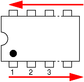
BYPASSED: Input --> FS4 --> FS9 --> FS8 --> Output

ENGAGED: Input --> FS4 --> FS5 --> PCB effect circuit --> FS7 --> FS8 --> Output

Warder wrote:
I pulled out my multi-meter to check resistance between R19 and FS7, before the resistor, the expected 1k, after the resistor 1 ohm, between FS7 and FS8, when the circuit is engaged, is 0.8 ohm and the resistance from FS8 to output is 0.9 ohm.

Those resistances all look good, assuming that you had the footswitch engaged.

What is the status of the bypassed signal path? This is what we should get resolved first, then worry about getting the effect circuit to work.

_________________
“My favorite programming language is SOLDER” - Bob Pease (RIP)

My Website * My Musical Gear * My DIY Pedals: Pg.1 - Pg.2


Top
 Profile  
 
PostPosted: Fri Apr 28, 2023 1:28 pm 
Offline

Joined: Wed Aug 10, 2022 11:17 pm
Posts: 28
The bypassed signal path works as you have detailed.

Before I checked anything else I hooked my audio probe up to the IN tip and the OUT tip, to make sure I hadn’t made a mistake when I built the probe, it seems I did not.

Let me try again. I checked most of the connection points in the PCB with the audio probe. The only one that seemed strange was that on the circuit side of R19 I had a strong signal, on the FS7 side of R19 (where the R19 pad connects to the trace that connects to Foot Switch Lug 7 (FS7)) I went from a strong clear signal to a muffled one at about a quarter the volume. Since FS7 connects to FS8 when the effect is engaged and then directly to the output, that volume loss is fed directly to output.

Put another way, when the signal passes through R19 it seems to be cut by 75% and then stuffed in a padded box. Before R19, strong signal, after R19, muffled signal.

I’m sorry I’m not being clear. I really appreciate your patience


Top
 Profile  
 
PostPosted: Fri Apr 28, 2023 2:33 pm 
Offline
Moderator
User avatar

Joined: Tue Jan 02, 2007 1:24 pm
Posts: 16232
Location: Albany, NY
OK, I think I'm up to speed now. Bypass works normally now, but when engaged, you're losing signal strength right near the end of the signal path.

Try this: temporarily disconnect the wire that connects the PCB to FS7 at the footswitch. Now test for signal right at the disconnected end of the wire. If you have full signal strength, the issue is happening in the footswitch, either a bad wire connection or an internal problem in the switch. If you still have a poor signal after R19 but a strong one before it, then it's either a bad resistor (rare, but possible) or a solder connection issue with it.

_________________
“My favorite programming language is SOLDER” - Bob Pease (RIP)

My Website * My Musical Gear * My DIY Pedals: Pg.1 - Pg.2


Top
 Profile  
 
PostPosted: Fri Apr 28, 2023 2:45 pm 
Offline

Joined: Wed Aug 10, 2022 11:17 pm
Posts: 28
Reflowed both R19 joints, which upon reflection was the thing to try as soon as I saw the problem.

I’m now getting signal, but I think I installed the drive pot incorrectly (wrong lugs to the wrong pads) b/c I’m getting feedback and all sorts of weird fuzz noises, off to check the build doc.


Top
 Profile  
 
PostPosted: Fri Apr 28, 2023 3:51 pm 
Offline

Joined: Wed Aug 10, 2022 11:17 pm
Posts: 28
Well, the drive pot is correctly wired, so now I’m getting weird fuzzy feedback and I have no idea why.


Top
 Profile  
 
PostPosted: Fri Apr 28, 2023 6:02 pm 
Offline
Moderator
User avatar

Joined: Tue Jan 02, 2007 1:24 pm
Posts: 16232
Location: Albany, NY
Please take a full set of pin voltages on the charge pump (lower left IC).With the black probe on ground, touch the red probe to each of the 8 IC pins and record the DC voltage seen at each one. See image below for the numbering of the pins. Be aware that there should be NEGATIVE voltages on a couple of the pins, so be sure to check for that on the meter display. Post your results here.

Image

_________________
“My favorite programming language is SOLDER” - Bob Pease (RIP)

My Website * My Musical Gear * My DIY Pedals: Pg.1 - Pg.2


Top
 Profile  
 
PostPosted: Fri Apr 28, 2023 7:22 pm 
Offline

Joined: Wed Aug 10, 2022 11:17 pm
Posts: 28
DC Voltage per pin on Charge Pump:

1. 9.2V
2. 5.364V
3. 0.001V
4. -3.664V
5. -8.79V
6. 4.242V
7. 5.7V
8. 9.2V


Top
 Profile  
 
Display posts from previous:  Sort by  
Post new topic Reply to topic  [ 39 posts ]  Go to page 1, 2  Next

All times are UTC - 6 hours


Who is online

Users browsing this forum: No registered users and 8 guests


You cannot post new topics in this forum
You cannot reply to topics in this forum
You cannot edit your posts in this forum
You cannot delete your posts in this forum
You cannot post attachments in this forum

Search for:
Jump to:  
Powered by phpBB® Forum Software © phpBB Group