Build Your Own Clone Message Board

It is currently Thu Apr 18, 2024 9:30 am

All times are UTC - 6 hours


Post new topic Reply to topic  [ 40 posts ]  Go to page Previous  1, 2
Author Message
PostPosted: Mon Aug 28, 2017 7:26 pm 
Online
Moderator
User avatar

Joined: Tue Jan 02, 2007 1:24 pm
Posts: 16216
Location: Albany, NY
Here's something else you might want to try, seeing as how we've come up with a whole lotta nuthin' on this so far:

I was a bit surprised at the wide range of collector voltages (posted above) that I measured on Q1, 2 and 3 on my RH Li'l Beaver. This prompted me to check the voltages on my other two Li'l Beavers, a Triangle and a NYC. These showed much tighter collector voltages, all in the range of 3.8 - 4.7V. It also prompted me to test the sound of the pedals side-by-side. What I found was that the RH had noticeably less output and sustain than the other two; this was especially evident with the sustain control down around 50% of its sweep. At the 100% sustain setting, the difference was far less dramatic but still very noticeable.

I compared notes with Keith (Mr. BYOC) on these observations, and he noted that raising the value of R3 would drop the collector voltage on Q1 and might even up the bias voltages between the transistors. Based upon that, I replaced the 43K resistor at R3 with a 51K (~20% higher resistance). This resulted in noticeably better sustain from the pedal (still not as much as the Triangle or the NYC, but they both have higher stage gains) and also a tighter range of collector voltages. The Q1 collector was reduced from 7.3 to 6.5V and Q3's increased from 2.9 to 4.0V. This change would also slightly raise (by ~7%) the input signal at the base of Q1 per the voltage divider effect mentioned by Markw1, but I doubt that that was a significant effect.

You may wish to try this R3 substitution and see if your pedal's performance is audibly improved. There is nothing magical about the 51K value I chose--I just wanted to increase it by ~20%. Other versions of the Big Muff circuit go as high as 100K there, so you may wish to experiment. You could even temporarily install a 100K pot there (if so, I'd recommend a linear taper) and vary the resistance until you get the output that sounds best to your ear. Then measure the resistance through the pot at that setting and install a fixed resistor of the same or similar value.

_________________
“My favorite programming language is SOLDER” - Bob Pease (RIP)

My Website * My Musical Gear * My DIY Pedals: Pg.1 - Pg.2


Top
 Profile  
 
PostPosted: Mon Aug 28, 2017 7:30 pm 
Offline

Joined: Fri May 29, 2015 7:28 am
Posts: 21
Duhvoodooman, sorry about that. You did not mis-speak. I mis-read. As I read back through your signal tester instructions, I realize that I combined two sentences that were never meant to go together. My bad.


Top
 Profile  
 
PostPosted: Mon Aug 28, 2017 8:58 pm 
Offline

Joined: Fri May 29, 2015 7:28 am
Posts: 21
Good idea on the resistor substitution. I may give that a whirl.

It still seems odd to me that my Large Beaver, built to Ram's Head specs, with the tone rotary switch set to mid-cut, like the originals, sounds so much better. I'd think they'd be closer. But this may be one of those mysteries of the universe that I am not meant to fathom.

Out of curiosity, I checked the schematic of the Large Beaver (Ram's Head), and noted some differences in the input stage, but perhaps they don't matter that much. Specifically, R1 = 1 meg; C1 = 10uf; R6 = 120. And, oddly enough, the thing that was the same is R3 = 43K, which is what is in the L'il Beaver. Lord only knows!

Thanks for everyone's help! I appreciate you guys jumping in.


Top
 Profile  
 
PostPosted: Tue Aug 29, 2017 11:40 am 
Online
Moderator
User avatar

Joined: Tue Jan 02, 2007 1:24 pm
Posts: 16216
Location: Albany, NY
You may find it interesting to look through Kit Rae's Big Muff History website, specifically the page devoted to the many Ram's Head versions: http://www.kitrae.net/music/big_muff_hi ... l#RamsHead

You'll see schematics shown for no less than seven different RH versions sold by Electro Harmonix between '73 and '76. Only the last two have the lower (<50Kohms) resistor values for R3 (labeled as R14 in these particular schematics); the first five all have the same 100K value that was used in most of the original Triangle version Muffs. In fact, he states that the most common version of the various RH Muff versions was the ca. 1973 "violet" Ram's Head, which used a 100K in that position.

My point here is just that there is nothing that says that a "vintage-correct" Ram's Head circuit needs to use the lower resistance value at this position. In fact, the 100K value appears to be more commonly used in the RH over its production span from '73 to '77.

_________________
“My favorite programming language is SOLDER” - Bob Pease (RIP)

My Website * My Musical Gear * My DIY Pedals: Pg.1 - Pg.2


Top
 Profile  
 
PostPosted: Tue Aug 29, 2017 5:55 pm 
Offline

Joined: Tue May 24, 2016 11:16 am
Posts: 104
The usual reason for having a resistor where R3 is, is because of Iceo (leakage current from collector to base). Without a resistor to drain away the leakage current, it would be amplified by transistor Beta. Too much of that could cause a significant shift in the bias operating point, or in the worst case thermal runaway. Depending on the particular transistors being used, required operating temperature range (outdoor concert in the sun on a hot day?), etc., somebody has to decide what is an appropriate value.

Beyond that basic circuit function (helping provide for transistor operating point stability), R3 could be reduced in value as an easy way to lower gain a little.


Top
 Profile  
 
PostPosted: Thu Aug 31, 2017 7:33 am 
Offline

Joined: Fri May 29, 2015 7:28 am
Posts: 21
All,

I found a review of the L'il Beaver Ram's Head on some site, Tone Print I think. The guy doing the review presumably was using L'il Beaver that had been built correctly. His only criticism of the pedal was that even with the Sustain control all the way up, the pedal did not seem to have the same sustain he was used to from Big Muff's and sustained notes seemed to "collapse" sooner than normal. So it may be, that I have a L'il Beaver that's functioning as designed. However, I'm still not thrilled with the sound.

I'm going to try upping the R3 resistor to 100k, as has been suggested. Also, can someone please tell me what the R1 resistor is meant to accomplish. It appears that it would shunt some of the input signal through the resistor to ground (by the way, I have no idea what I'm talking about). I noticed that most if not all of Muff RH schematics on Kit Rae's site do not have this resistor. So I'm considering clipping it out as well. Thoughts?


Top
 Profile  
 
PostPosted: Thu Aug 31, 2017 8:18 am 
Offline

Joined: Tue May 24, 2016 11:16 am
Posts: 104
R1 has very little effect one way or the other in most cases. It provides a way to discharge any DC voltage on the input capacitor. In most cases a guitar would serve that function, but perhaps putting another pedal in front of this pedal would leave it with no DC path to ground for the capacitor.

For more gain, R3 could be a little bigger and R4 maybe also a little bigger, but that will change the tone too. R5 might be increased as well to maybe 15k, at least if R4 is increased or removed.

If you want to find out what more gain before the two distortion transistors Q2 and Q3 sounds like, you could put a clean gain boost pedal of some type before the Ram's Head. That would give you an idea of what increasing the gain at or around Q1 would sound like.

Have fun with your experiments. Personally, I find that sustain and tone are often trade offs. More of one may give less of the other.

Standing in front of the guitar amp with the volume cranked up can give some acoustical feedback, and that can provide very long sustain.

A compressor can help too, by pulling up the gain as the guitar signal decays. Putting one before the Ram's Head would help keep the level up, but might also reduce the swish as you play rhythm.

Putting a delay pedal after a distortion pedal often increases apparent sustain while giving good tone.

Sustain also depends on the particular guitar and strings used.

Also, remember than recordings you may listen too may have studio tricks on them to increase sustain. Probably not exactly how live sound would be.


Top
 Profile  
 
PostPosted: Thu Aug 31, 2017 8:41 am 
Online
Moderator
User avatar

Joined: Tue Jan 02, 2007 1:24 pm
Posts: 16216
Location: Albany, NY
Cirlot wrote:
I found a review of the L'il Beaver Ram's Head on some site, Tone Print I think. The guy doing the review presumably was using L'il Beaver that had been built correctly. His only criticism of the pedal was that even with the Sustain control all the way up, the pedal did not seem to have the same sustain he was used to from Big Muff's and sustained notes seemed to "collapse" sooner than normal.

Just read that review--it's HERE on the Tone Report website. His description seems to match your observations very closely, and I understand where he's coming from based on my own pedal. His theory about the pedal containing some sort of noise suppression circuit is completely wrong, however. The pedal contains a Big Muff circuit, period. Until shown otherwise, I still believe that the reduced sustain of this particular version of the Li'l Beaver is related to that low R3 value and the apparent effect it has on the voltage biasing of the transistors.

Cirlot wrote:
Also, can someone please tell me what the R1 resistor is meant to accomplish. It appears that it would shunt some of the input signal through the resistor to ground (by the way, I have no idea what I'm talking about). I noticed that most if not all of Muff RH schematics on Kit Rae's site do not have this resistor. So I'm considering clipping it out as well. Thoughts?

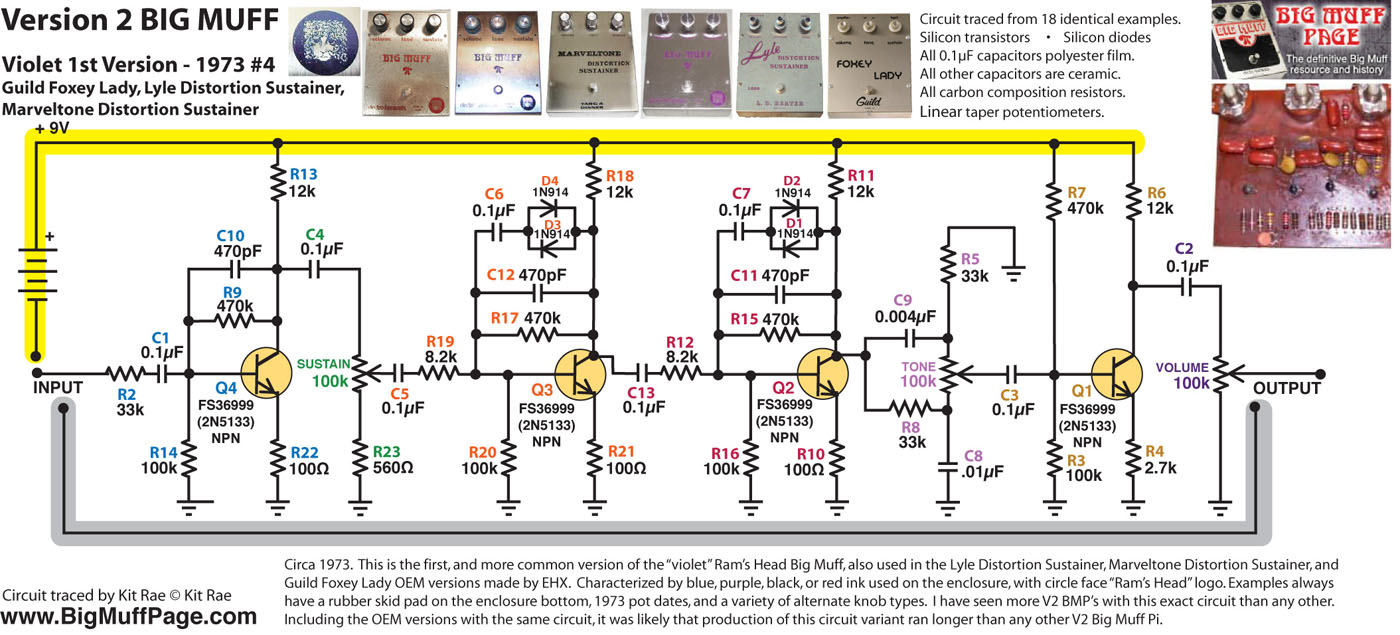
I recommend against clipping out R1. Its primary function is to bleed off any DC voltage present at the input and avoid popping when the effect is engaged. At 470K, it has a negligible effect on the incoming signal. I'm not sure if this resistor wasn't present in those early Muffs or if the Kit Rae schematics just leave it out since it serves no function within the actual effect circuit. Note that R1 isn't shown in any of those schematics--they all start with the input series resistor that's labeled R2. And it's present in all of the Li'l Beaver versions and in the original BYOC Large Beaver.

P.S. You might be interested in THIS PDF DIAGRAM on the Kit Rae site that explains the functions of the various elements of the Big Muff circuit. But there's a ton more good info on THAT WHOLE PAGE.

And if you want to get deeply into the theory of how it works, there's THIS ARTICLE on the ElectroSmash site (WARNING! Contains algebra! :wink: ).

_________________
“My favorite programming language is SOLDER” - Bob Pease (RIP)

My Website * My Musical Gear * My DIY Pedals: Pg.1 - Pg.2


Top
 Profile  
 
PostPosted: Thu Aug 31, 2017 10:52 am 
Online
Moderator
User avatar

Joined: Tue Jan 02, 2007 1:24 pm
Posts: 16216
Location: Albany, NY
I just changed R3 on my RH Li'l Beaver to 100K, and it makes a substantial improvement to the sustain as well as evening out the collector voltages on Q1, 2 and 3. The latter are now 4.2V, 4.1V and 4.0V, in that order. I would recommend this change to anyone looking for greater sustain from the RH version of the Li'l Beaver. My Triangle and NYC versions still show somewhat greater saturation and sustain, but I believe this is just a reflection of the higher transistor stage gains in those two versions of the circuit.

_________________
“My favorite programming language is SOLDER” - Bob Pease (RIP)

My Website * My Musical Gear * My DIY Pedals: Pg.1 - Pg.2


Top
 Profile  
 
PostPosted: Fri Mar 27, 2020 12:31 pm 
Offline

Joined: Tue Sep 11, 2018 11:10 am
Posts: 188
duhvoodooman wrote:
I just changed R3 on my RH Li'l Beaver to 100K, and it makes a substantial improvement to the sustain as well as evening out the collector voltages on Q1, 2 and 3. The latter are now 4.2V, 4.1V and 4.0V, in that order. I would recommend this change to anyone looking for greater sustain from the RH version of the Li'l Beaver. My Triangle and NYC versions still show somewhat greater saturation and sustain, but I believe this is just a reflection of the higher transistor stage gains in those two versions of the circuit.

I know this post is old but I had a question regarding this issue so I thought I'd throw it out there. I replaced the R3 with a 100K resistor and it is much better. BUT, it still doesn't hold the note as long as the Large Beaver does. Will a larger resistor help or is there something else I can change? Or is the 100K about the best I can do?

_________________
-Jamie


Top
 Profile  
 
PostPosted: Fri Mar 27, 2020 3:31 pm 
Online
Moderator
User avatar

Joined: Tue Jan 02, 2007 1:24 pm
Posts: 16216
Location: Albany, NY
Is your Large Beaver the Ram's Head version, too?

_________________
“My favorite programming language is SOLDER” - Bob Pease (RIP)

My Website * My Musical Gear * My DIY Pedals: Pg.1 - Pg.2


Top
 Profile  
 
PostPosted: Fri Mar 27, 2020 3:35 pm 
Offline

Joined: Tue Sep 11, 2018 11:10 am
Posts: 188
duhvoodooman wrote:
Is your Large Beaver the Ram's Head version, too?

Yes.

_________________
-Jamie


Top
 Profile  
 
PostPosted: Mon Mar 30, 2020 12:08 pm 
Offline

Joined: Tue Sep 11, 2018 11:10 am
Posts: 188
duhvoodooman wrote:
Is your Large Beaver the Ram's Head version, too?

Just bumping this... Any ideas on improving the sustain on the Li'l Beaver Ram's Head? To be clear, I'm comparing it to the Big Beaver Ram's Head which does not collapse notes. Even with the R3 100K replacement, the Li'l Beaver Ram's Head is collapsing notes though it does take longer for it to happen with the 100K. The Big Beaver Ram's Head does not do this at all. If there is anything else I can try to do to improve this, I'm willing to do so.

_________________
-Jamie


Top
 Profile  
 
PostPosted: Mon Mar 30, 2020 12:17 pm 
Online
Moderator
User avatar

Joined: Tue Jan 02, 2007 1:24 pm
Posts: 16216
Location: Albany, NY
Please start a NEW thread (we try our best not to piggyback problems together here, even when they seem to be the same), describe your issue in detail there and provide some photos. These need to be LARGE, well-lit, well-focused shots of BOTH sides of the PCB and all of your switch and jack wiring. A lack of sustain such as you describe could be caused by more than just the R3 resistor. We need to be sure we look at the potential cause more broadly than that. Thanks!

_________________
“My favorite programming language is SOLDER” - Bob Pease (RIP)

My Website * My Musical Gear * My DIY Pedals: Pg.1 - Pg.2


Top
 Profile  
 
PostPosted: Mon Mar 30, 2020 12:31 pm 
Offline

Joined: Tue Sep 11, 2018 11:10 am
Posts: 188
duhvoodooman wrote:
Please start a NEW thread (we try our best not to piggyback problems together here, even when they seem to be the same), describe your issue in detail there and provide some photos. These need to be LARGE, well-lit, well-focused shots of BOTH sides of the PCB and all of your switch and jack wiring. A lack of sustain such as you describe could be caused by more than just the R3 resistor. We need to be sure we look at the potential cause more broadly than that. Thanks!

Will do.

EDIT: Here's the new thread...

viewtopic.php?f=51&t=58490&p=490657#p490657

_________________
-Jamie


Top
 Profile  
 
Display posts from previous:  Sort by  
Post new topic Reply to topic  [ 40 posts ]  Go to page Previous  1, 2

All times are UTC - 6 hours


Who is online

Users browsing this forum: No registered users and 4 guests


You cannot post new topics in this forum
You cannot reply to topics in this forum
You cannot edit your posts in this forum
You cannot delete your posts in this forum
You cannot post attachments in this forum

Search for:
Jump to:  
cron
Powered by phpBB® Forum Software © phpBB Group