Build Your Own Clone Message Board

It is currently Sun Apr 28, 2024 8:53 am

All times are UTC - 6 hours


Post new topic Reply to topic  [ 5 posts ] 
Author Message
 Post subject: Signal tester. :)
PostPosted: Thu Oct 20, 2022 4:22 pm 
Offline

Joined: Mon Nov 23, 2020 1:39 pm
Posts: 183
Location: Vermont
I realize you guys love "guts shots" and I haven't been pulling my weight around here. So without further ado, here's a little project I threw together last night, inspired by the famous Signal Tester that unfortunately is out of stock.

Attachment:
thumbnail_IMG_0245.jpg
thumbnail_IMG_0245.jpg [ 70.23 KiB | Viewed 7606 times ]


I use it with banana plug test leads I already had.

Attachment:
thumbnail_IMG_0246.jpg
thumbnail_IMG_0246.jpg [ 107.48 KiB | Viewed 7606 times ]


Top
 Profile  
 
 Post subject: Re: Signal tester. :)
PostPosted: Thu Oct 20, 2022 6:02 pm 
Offline
Moderator
User avatar

Joined: Tue Jan 02, 2007 1:24 pm
Posts: 16224
Location: Albany, NY
Nice! Looks highly functional! :mrgreen:

_________________
“My favorite programming language is SOLDER” - Bob Pease (RIP)

My Website * My Musical Gear * My DIY Pedals: Pg.1 - Pg.2


Top
 Profile  
 
 Post subject: Re: Signal tester. :)
PostPosted: Thu Apr 27, 2023 3:24 pm 
Offline

Joined: Mon Nov 23, 2020 1:39 pm
Posts: 183
Location: Vermont
At the other end of the scale, here is a minimalist way of getting the signal tester functionality, requiring only a capacitor and some hookup wire (also solder and a soldering iron, but presumably everybody here has those). It requires a slight modification of the pedal and is not portable from one pedal to another (until you are done with it and de-solder it from your pedal under test), but I offer this as a way to help out the new builder who may not have lots of spare parts lying around (as I did when I cobbled together the widget in the opening post).

(1) Get a capacitor. Best would be a non-polarized cap in the 0.01 uF (10 nF) to 1.0 uF (1000 nF) range but go lower if you have to.

For this exercise I decided to raid an expired household device circuit board. I noted that one bulky cap was marked "224" so knew there was a good chance it would be ~ 220 nF and hence appropriate. (I also set my sights on grabbing a resistor in case I needed a pull-down to avoid "pops" when using the device; I noted that both the Bass Chorus and the Green Pony, two pedals as of this writing under "discussion" in troubleshooting threads, have 100 kohm in this role so I searched for the same on the board [brown-black-yellow], and, remarkably, one was nearby. Spoiler: In the end the "pops" did not bother me so I didn't bring the resistor into play, but it is still in some of my photos.)

Attachment:
(16) to_be_harvested_2_sm.JPG
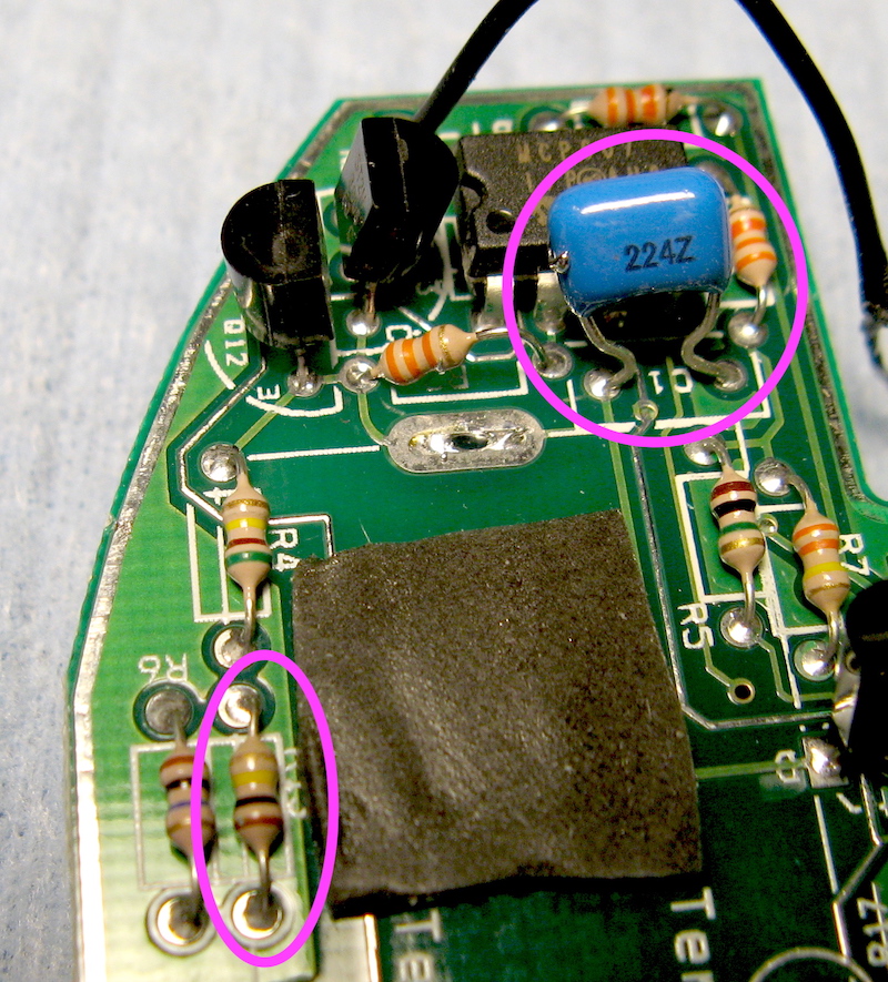
(16) to_be_harvested_2_sm.JPG [ 479.34 KiB | Viewed 6595 times ]


After encouraging my solder sucker with a few choice words, I had my parts. I have meters for measuring resistance and capacitance and the values were confirmed.

Attachment:
(17) raw_fruit.JPG
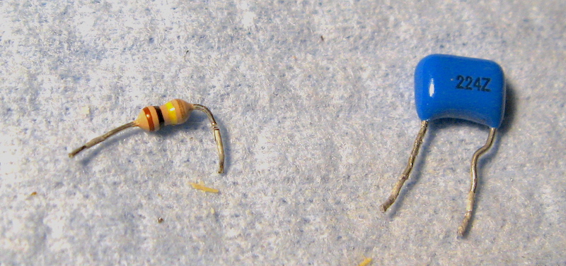
(17) raw_fruit.JPG [ 207.67 KiB | Viewed 6595 times ]


(2) The original board-stuffer trimmed the leads, of course, so next I soldered on some lengths of buss wire (can use your own discarded trimmings, just as well) to make the components a little easier to wrangle.

Attachment:
(18) new leads.JPG
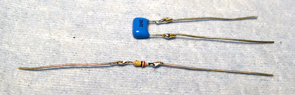
(18) new leads.JPG [ 223.35 KiB | Viewed 6595 times ]


There seems to be a limit on the number of photos per post, so I will pick up the story here in my next installment.


Last edited by WMP1 on Fri Apr 28, 2023 6:15 am, edited 1 time in total.

Top
 Profile  
 
 Post subject: Re: Signal tester. :)
PostPosted: Thu Apr 27, 2023 3:34 pm 
Offline

Joined: Mon Nov 23, 2020 1:39 pm
Posts: 183
Location: Vermont
(3) Next I added, to one lead of the capacitor, a length of hookup wire to serve as the "probe" part of the operation. I used solid wire so that it would have some natural stiffness, but stranded is okay too; you just would need to dress the end properly. One way would be to tin it normally; another would be to solder onto it a stiff pin of some sort.

Attachment:
(19) minimal signal tester.JPG
(19) minimal signal tester.JPG [ 424.08 KiB | Viewed 6593 times ]


(Yeah, I do like my heat-shrink tubing ... You can omit it, but just be careful not to make some short circuits somewhere.)

And that's basically it ... except, of course, how do you hook it into where it needs to go? Best would be to use a spare 1/4-inch jack if you have one (combined with a still-good guitar cable), or most of a retired guitar cable, but in the spirit of "I don't have anything except a capacitor I managed to scare up from somewhere" I will show you how to use your pedal's output jack for that purpose.

And I would not ask you to do something I would not myself do, so here's how it looks in my own Bass Chorus pedal.

First, the guts of the stock pedal, with the wires sorted so you can see the key wire from footswitch lug 8 to the output jack "tip" lug.

Attachment:
(20) Bass Chorus stock.JPG
(20) Bass Chorus stock.JPG [ 421.2 KiB | Viewed 6593 times ]


The output jack "tip" lug needs to be disconnected from footswitch lug 8. Like so:

Attachment:
(21) output unchained.JPG
(21) output unchained.JPG [ 437.45 KiB | Viewed 6593 times ]


In the next post, the signal tester gets installed and used.


Last edited by WMP1 on Thu Apr 27, 2023 3:47 pm, edited 1 time in total.

Top
 Profile  
 
 Post subject: Re: Signal tester. :)
PostPosted: Thu Apr 27, 2023 3:45 pm 
Offline

Joined: Mon Nov 23, 2020 1:39 pm
Posts: 183
Location: Vermont
(4) Now install the signal tester. The lead of the capacitor that is NOT connected to the long probe wire instead gets connected to the output jack "tip" lug. In this way, whatever point in the circuit gets tickled by the test probe wire, is the point from which a signal gets sent to the output jack (and then to your amp). The wire from footswitch lug 8 is just hanging out, hoping someday to once again be able to monopolize the output scene.

Attachment:
(25) ready.JPG
(25) ready.JPG [ 599.36 KiB | Viewed 6593 times ]


And that's it.

Here is one last photo, of me using the tester to see (hear!) just what is going on at pin 7 of the 4558 dual op amp in the Bass Chorus. You can't hear it, but I did, and it was indeed a luscious chorus-y kind of sound. The expected results were also found at pin 1 (the original signal, essentially) and at the 3207 pins 3 and 7/8 (pre- and post-BBD treatment).

Attachment:
(27) 4558 pin 7.JPG
(27) 4558 pin 7.JPG [ 376.23 KiB | Viewed 6593 times ]


---------------------------------

I don't consider this to be a proper substitute for a stand-alone signal tester, along the lines of what BYOC used to stock, or its variants such as the thing I illustrated earlier. But in a pinch, it can serve the same purpose.


Top
 Profile  
 
Display posts from previous:  Sort by  
Post new topic Reply to topic  [ 5 posts ] 

All times are UTC - 6 hours


Who is online

Users browsing this forum: No registered users and 5 guests


You cannot post new topics in this forum
You cannot reply to topics in this forum
You cannot edit your posts in this forum
You cannot delete your posts in this forum
You cannot post attachments in this forum

Search for:
Jump to:  
Powered by phpBB® Forum Software © phpBB Group