Okay, not a BYOC pedal, but one of my own.
This is a Hornby Skewes/Blackmore inspired Ge Treble Booster. The Ge Hornby Skewes is what Blackmore first used prior to changing to a Si based HS booster (of which I have built 3). I could not find a nailed down, official schematic for the Ge version and there appears to have been some changing of components or slight differences in schematics. I used schematics found on the internet as well as gutshot photos of originals. Some had a 1K Emitter Resistor while others had ones with a 2.2K value. The photos showed Emitter Resistor Bypass Capacitor values of 100uF and 125uF, which would be needed for a 1K Emitter Resistor value, but using a 2.2uF Emitter Resistor, calculations show that a 47uF would suffice in this situation and is what I used. The old schematics showed fixed 100K and 10K resistors for the bias network (0.8V base voltage), but I chose a 30K trimmer which I had on hand to set a base voltage of around 1.1V similar to a Rangemaster. Below is my base working schematic diagram.

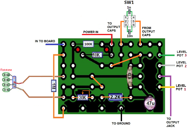
I further altered the circuit through experience building Hornby Skewes like boosters and added a “Thick” switch to the output capacitor to change from the standard 1n value to a 10n value, which “thickens up” the sound to my ears. Also, I used a Rotary switch that changes between different input caps (10n, standard 22n, 33n and 47n) in order to get various tonal variations from the pedal. Blackmore supposedly had the input cap on his pedal changed, possibly to 47n, but nobody knows for sure. The 10n setting gives the pedal more of a Rangemaster sound. For me, this pedal is very versatile as a treble booster. The PCB board layout is below, if anyone cares to build a similar one.
In the gutshot below, you can see the bias trimmer mounted on the inside wall of the box, the output cap switch at the top, Rototone in the middle and the HS GBOF circuit PCB at the top corner over the boost control pot. A 100 HFE NPN Germanium transistor obtained from Small Bear is mounted in the sockets. Below is the finished exterior. Just love this pedal for classic treble boosted tones!


I would like to thank BYOC for starting me on the journey (basically an addiction) of building and modifying pedals for the past 15 years or so (I built my first one - a BYOC ESV Fuzz Face around 2006 or 2007). I have now built 41 pedals over that time and have about 9-10 more in the pipeline.


