As great as the BYOC Brit 45 and 50 amp kits are, they lack the same feature as most fixed bias amp kits: the ability to re-bias the output tubes without going into the chassis. This is not only FAR more convenient than having to pull the chassis out of the cabinet to re-bias the amp, but it's also a safety enhancement, since you're not exposed to the high DC voltage-bearing parts of the amp circuit during the biasing operation. I also own an Allen Sweet Spot combo amp that I built from the kit, and David Allen included this external biasing capability in the kit. There's nothing complex about it--it's just a matter of mounting test ports through the chassis to do the current biasing measurement, as well as installing a pot through the chassis wall so that the bias current adjustment can be made externally.
I'm currently in possession of a modified BYOC Brit 45 head that I'm preparing to put up for sale (it's a L-O-O-O-O-N-N-G-G story) and decided that this would be an excellent feature to add to the amp. So read on if you're interested to see how I did it....
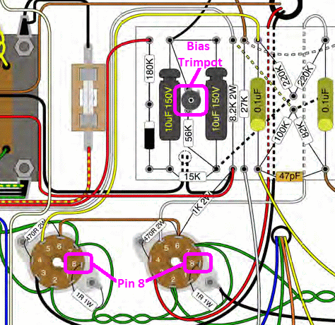
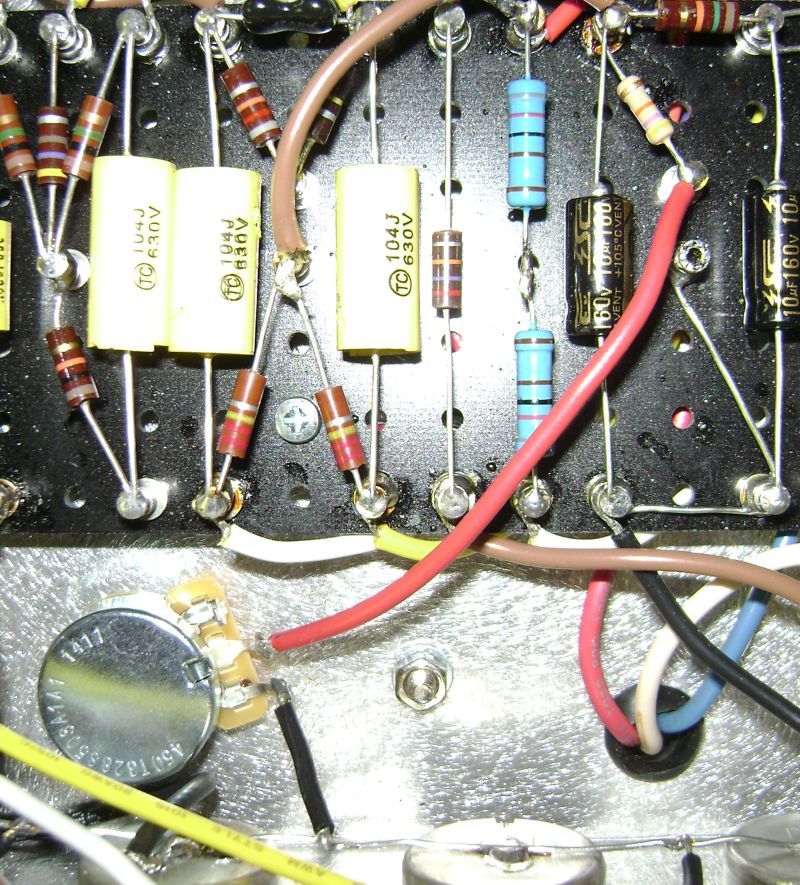
The Brit 45 and 50 kits share the same output tube biasing set-up, namely a trimpot and fixed resistor in series connecting to ground between the two output tube grid resistors. Adjustment of this trimpot determines the plate current in the output tubes, which should be set within a range determined by maximum plate dissipation wattage spec for the tube type. For fixed bias class A/B amps, the optimal range is generally within 60 - 70% of the tube's max. dissipation wattage value, where you get a nice balance between good rich tone and reasonable output tube life. Without getting into all the math here, for the KT66 or EL34 tubes used in the Brit 45 and 50 amps, this all translates to a plate current value of 33 - 39mA.
The way the plate current is measured is by taking the voltage drop reading across a 1.0 ohm resistor that is connected between the tube cathode (pin 8 ) and ground on each output tube. This resistor value is chosen because it makes the voltage reading across the resistor in millivolts (mV) equal to the plate current in milliamps (mA). In other words, if you want 39mA of plate current, adjust the trimpot to give 39mV across each resistor. In practice, it's not generally possible to get exactly the same current through both tube plates, since the tubes are not identical, even when purchased as a "matched" pair. I usually adjust the plate current so that the average of the two tubes hits my target value.
For the Brit 45 and 50 kit builds in stock configuration, this adjustment is made by measuring the voltage drop between pin 8 of one of the output tubes and ground, and then
slowly/carefully adjusting the trimpot (see marked up photo below) to give the desired mV value on your multimeter. Repeat this process for the second tube (assuming you have two output tubes; the same basic procedure can be used for 4 output tubes) and adjust the trimpot as needed.
The modification consists of:
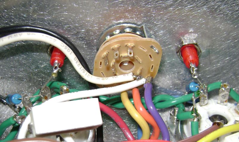
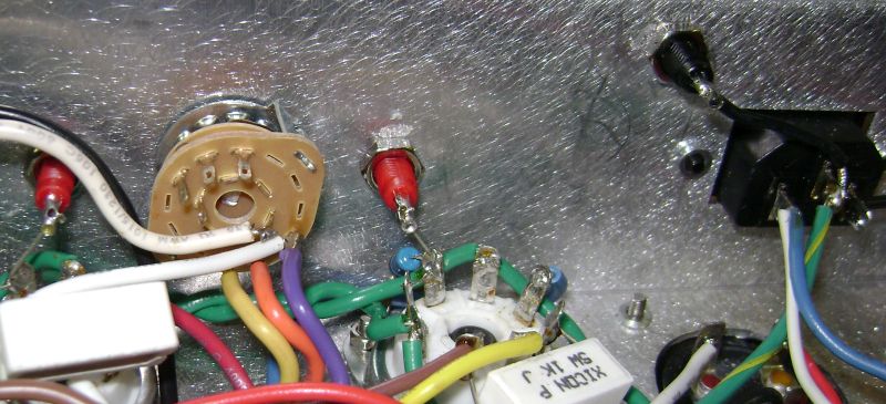
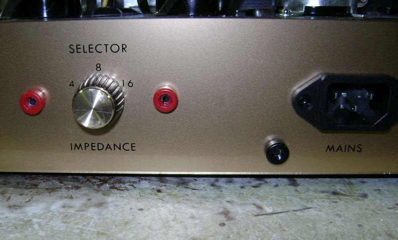
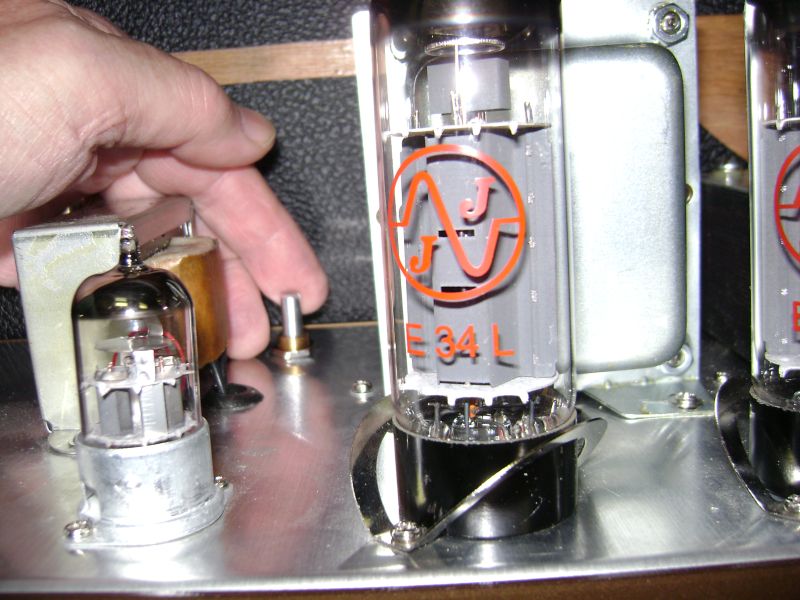
- Installation of test probe ports through the rear panel of the amp (two for the pin 8 connections to the output tubes and one for a ground connection). I used red body ports (Mouser # 530-105-0802-1) for the two pin 8 connections and a black body port (Mouser # 530-105-0803-1) for the ground connection. This involves drilling through the rear plexi plate as well as the chassis. which needs to be done CAREFULLY. I used a series of increasing diameter drills until I got to the 1/4" hole required for the port, and drilled s-l-o-w-l-y, to avoid melting the plexiglas and damaging the plate. I positioned the two tube pin ports on either side of the output impedance rotary switch, which puts the ports right adjacent to their respective tube sockets. The tip of each port was then wired to pin 8 (or pin 1, since the two pins are connected) of the corresponding tube socket. For additional convenience, I also installed a ground port through the chassis next to the mains socket and wired it to the ground tab of that socket. See the photos below for inside and outside view of the test port installation:
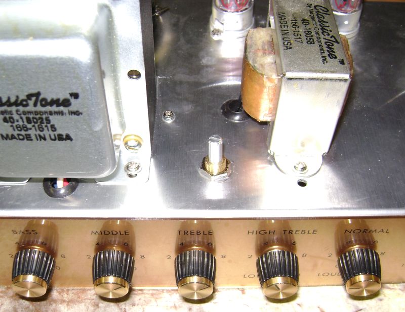
- Replacement of the trimpot on the turret board with a CTS 50K linear solder lug pot (Mouser # 774-450T328S503A1A1) installed through the top of the chassis. I installed mine between the OT and the choke, since (a) there was space inside the chassis for the pot body and wire connections, and (b) the pot shaft was readily accessible from the back of the cabinet by reaching over the top of the preamp tubes. The trimpot was removed from the turret board, and the wiper of the new pot was wired to the turret with the fixed bias resistor connection. One of the outside lugs (it doesn't matter which one you use, since the pot is being used as a variable resistor) was then wired to ground; I used the ground bus on the back of the front panel pots for this connection. NOTE: At this point, I recommend turning the pot to the end of its sweep that gives the maximum resistance between the two connected lugs. This guarantees a low plate bias current on initial start-up, protecting the output tubes.
Here are a couple of shots showing the pot connections, chassis installation and ease of access through the back of the cabinet:
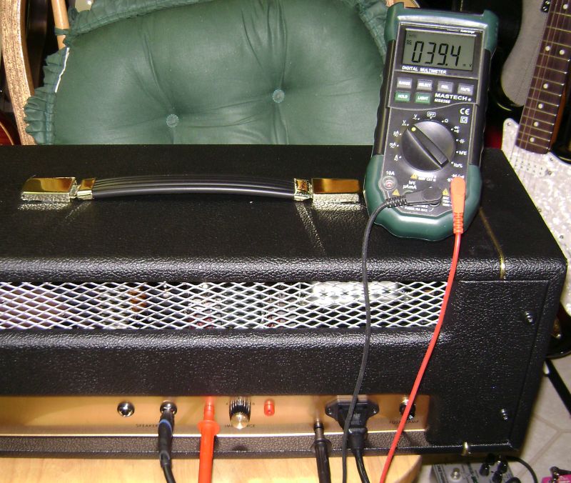
That's all there is to this very useful modification. Mount the chassis into the cabinet, fire up the amp (be sure to use the startup procedure in the Brit 45 & 50 instructions if this is the "maiden voyage"!), insert your multimeter probes in the test ports, and dial in the desired bias current value with the new pot. Here's how mine looked after this process:
_________________
“My favorite programming language is SOLDER” - Bob Pease (RIP)
My Website *
My Musical Gear * My DIY Pedals:
Pg.1 -
Pg.2


