Build Your Own Clone Message Board

It is currently Thu Apr 18, 2024 11:36 pm

All times are UTC - 6 hours


Post new topic Reply to topic  [ 23 posts ] 
Author Message
PostPosted: Thu Nov 23, 2017 8:49 pm 
Offline
Moderator
User avatar

Joined: Tue Jan 02, 2007 1:24 pm
Posts: 16220
Location: Albany, NY
Randomly working circuits are almost always due to an intermittent connection issue, and the most common cause that we see for that is a bad solder joint somewhere. I'd start by doing this: viewtopic.php?f=9&t=52188

I'd pay particular attention to the wire connections between the footswitch and the PCB--several of those connections on the PCB look pretty sparse, and could probably use some additional solder.

_________________
“My favorite programming language is SOLDER” - Bob Pease (RIP)

My Website * My Musical Gear * My DIY Pedals: Pg.1 - Pg.2


Top
 Profile  
 
PostPosted: Thu Nov 23, 2017 9:49 pm 
Offline
Moderator
User avatar

Joined: Tue Jan 02, 2007 1:24 pm
Posts: 16220
Location: Albany, NY
chongmagic wrote:
Could it be that the footswitch is bad?

Sure, it's possible, but it doesn't happen very often. But it's easy enough to check if it's working. Do you have access to a multimeter and know how to measure continuity with one?

_________________
“My favorite programming language is SOLDER” - Bob Pease (RIP)

My Website * My Musical Gear * My DIY Pedals: Pg.1 - Pg.2


Top
 Profile  
 
PostPosted: Fri Nov 24, 2017 11:45 am 
Offline
Moderator
User avatar

Joined: Tue Jan 02, 2007 1:24 pm
Posts: 16220
Location: Albany, NY
OK then, use your multimeter to due a basic functionality test on the footswitch. With the switch in the engaged position, check for continuity between lugs 4 & 5 and between lugs 7 & 8. These are the signal paths into (4 --> 5) and out of (7 --> 8 ) the effect circuit on the PCB. When you take the readings, place your probes on the top of the lug itself, not the solder joint. The lug numbering is as shown below:

Image

_________________
“My favorite programming language is SOLDER” - Bob Pease (RIP)

My Website * My Musical Gear * My DIY Pedals: Pg.1 - Pg.2


Top
 Profile  
 
PostPosted: Fri Nov 24, 2017 4:59 pm 
Offline
Moderator
User avatar

Joined: Tue Jan 02, 2007 1:24 pm
Posts: 16220
Location: Albany, NY
chongmagic wrote:
I'm still pretty new at soldering, from a more experienced viewpoint is it bad?

Not too bad overall, but there are several questionable joints. See marked up photo below. What you want is a shiny, cone-shaped joint, kind of like a miniature volcano or a Hershey Kiss. If you can clearly see the shape of the PCB eyelet through the joint, that's asking for trouble. Several of the joints for the footswitch wires at the bottom of the PCB and for the 14-pin IC fit this description. Blobby, irregular or rough looking joints should be re-done, as well as any that fail to completely cover the solder pad of the PCB. And be careful that there isn't any solder "bridging" between the adjacent joints under the electrolytic caps. I've circled a couple of those that should be carefully inspected.

Attachment:
mimosa_soldering.jpg
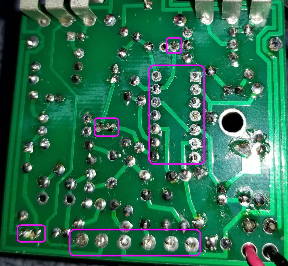
mimosa_soldering.jpg [ 174.2 KiB | Viewed 5308 times ]

_________________
“My favorite programming language is SOLDER” - Bob Pease (RIP)

My Website * My Musical Gear * My DIY Pedals: Pg.1 - Pg.2


Top
 Profile  
 
PostPosted: Sat Nov 25, 2017 11:54 am 
Offline
Moderator
User avatar

Joined: Tue Jan 02, 2007 1:24 pm
Posts: 16220
Location: Albany, NY
chongmagic wrote:
Also the top that is circled is the ceramic cap should I have soldered it into the first and last solder pads or is it OK as it is?

Fine as is--those two solder pads are connected; they are there to accommodate ceramic caps with different lead spacing.

_________________
“My favorite programming language is SOLDER” - Bob Pease (RIP)

My Website * My Musical Gear * My DIY Pedals: Pg.1 - Pg.2


Top
 Profile  
 
PostPosted: Sun Nov 26, 2017 2:43 pm 
Offline
Moderator
User avatar

Joined: Tue Jan 02, 2007 1:24 pm
Posts: 16220
Location: Albany, NY
That sounds correct--most of the IC pins sit at 1/2 of your power source voltage.

_________________
“My favorite programming language is SOLDER” - Bob Pease (RIP)

My Website * My Musical Gear * My DIY Pedals: Pg.1 - Pg.2


Top
 Profile  
 
Display posts from previous:  Sort by  
Post new topic Reply to topic  [ 23 posts ] 

All times are UTC - 6 hours


Who is online

Users browsing this forum: No registered users and 1 guest


You cannot post new topics in this forum
You cannot reply to topics in this forum
You cannot edit your posts in this forum
You cannot delete your posts in this forum
You cannot post attachments in this forum

Search for:
Jump to:  
cron
Powered by phpBB® Forum Software © phpBB Group