Build Your Own Clone Message Board

It is currently Wed Apr 17, 2024 8:22 pm

All times are UTC - 6 hours


Post new topic Reply to topic  [ 20 posts ] 
Author Message
 Post subject: Crown Jewel Octave Up
PostPosted: Mon Aug 10, 2020 12:46 am 
Offline

Joined: Mon Aug 10, 2020 12:26 am
Posts: 2
Hi All,

Not sure if this is the right place for this but, I was planning on building a crown jewel and with covid creating supply chain issues I figured I would just buy the octave up module and build that immediately (I need to do stuff with my hands to keep me sane!) and building the crown jewel once it is in stock.

Since that may be a while away I was looking at the schematic to figure out if there's a way to make the module work just to double check I haven't stuffed anything up. From what I can tell the only thing that I would really need is a dropping resistor of some sort to produce the +4.5v.

Is this correct? and if it is correct can someone point me in the right direction to be able to calculate the size of the resistor?

Edit: So I was a bit quick to post - I looked at the crown jewel schematic and saw the 2 x 33k resistors, and the 47uf cap producing +4.5v. I'd still probably need someone to tell me if I'm on the right track as I'm not keen on breaking/stuffing anything up.

Many Thanks,
Tony


Top
 Profile  
 
PostPosted: Mon Aug 10, 2020 7:56 am 
Offline
Moderator
User avatar

Joined: Tue Jan 02, 2007 1:24 pm
Posts: 16216
Location: Albany, NY
Please clarify what you want to accomplish here. Are you talking about just building the Octave Up module and setting it aside, or building a stand-alone functioning pedal out of it?

_________________
“My favorite programming language is SOLDER” - Bob Pease (RIP)

My Website * My Musical Gear * My DIY Pedals: Pg.1 - Pg.2


Top
 Profile  
 
PostPosted: Sun Aug 23, 2020 6:32 am 
Offline

Joined: Mon Aug 10, 2020 12:26 am
Posts: 2
Sorry for the delayed response, I've been keeping busy.

I have built the octave up unit and have set it aside waiting for the crown jewel to come back into stock.

To check that the unit works (and I didn't stuff anything up) I'd like to turn it into a standalone unit.

Any help would be greatly appreciated.


Top
 Profile  
 
PostPosted: Sun Aug 23, 2020 5:24 pm 
Offline
Moderator
User avatar

Joined: Tue Jan 02, 2007 1:24 pm
Posts: 16216
Location: Albany, NY
The easiest way to do this would be to purchase the Crown Jewel Module "Daughter Board", which is set up to provide all of the various power options and connection points that the Octave Up or any of the other CJ modules would require to run as a stand-alone. See PCB image below.

Image

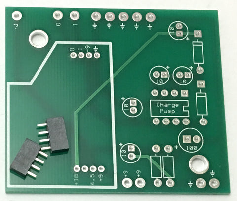
The bad news is that there are no instructions provided for this board, since it is typically being used by experienced builders who know exactly what to do with it. In addition to the Daughter Board, you'll also need several components as well as the hardware to make it functional:

Electronic components:

1 - 100uf electrolytic capacitor
5 - 10uf electrolytic capacitor
2 - 1N5817 Schottky diode (can substitute 1N4001 if not available)
2 - 10 Kohm metal film resistor
1 - DIP-8 socket
1 - charge pump IC (Max1044S, ICL7660S or LT1054; the "S" suffix is critical on those first two!)

Hardware:

1 - 1/4" stereo jack
1 - 1/4" mono jack
1 - DC adapter jack
1 - 3PDT footswitch
2 - self-adhesive standoffs (for mounting board in enclosure)
1 - A100K potentiometer (for volume control)
1 - 5mm LED (optional; color of your choice)
1 - battery snap (optional; skip if only using a DC adapter)
4 - self-adhesive rubber feet (optional)
1 - 1590B or 125B metal enclosure
Hook-up wire

I did this same basic thing a couple of times back just after the CJ & modules first came out, but I used the Experimenter board (much more complicated build) because the Daughter Board hadn't come out yet. But the photos in this thread should be helpful in showing how you can lay it all out:

viewtopic.php?f=9&t=54926

_________________
“My favorite programming language is SOLDER” - Bob Pease (RIP)

My Website * My Musical Gear * My DIY Pedals: Pg.1 - Pg.2


Top
 Profile  
 
PostPosted: Thu Aug 27, 2020 4:03 pm 
Offline

Joined: Thu Jul 18, 2019 7:51 am
Posts: 111
That's 5 10uf electrolytic, yes? And the 10k resistors go next to each other in the 2 unmarked rectangles...
Oh, what about the vol pot? From the line out to the pot, to the jack?
And what deos the volume control? The effect volume? The output of the higher Octave signal?


Top
 Profile  
 
PostPosted: Thu Aug 27, 2020 6:06 pm 
Offline
Moderator
User avatar

Joined: Tue Jan 02, 2007 1:24 pm
Posts: 16216
Location: Albany, NY
RobertJay wrote:
That's 5 10uf electrolytic, yes? YES. Corrected above post.

And the 10k resistors go next to each other in the 2 unmarked rectangles... YES

Oh, what about the vol pot? From the line out to the pot, to the jack? YES. Effect output to lug 3, lug 2 to the output jack tip, lug 1 to ground.

And what deos the volume control? The effect volume? The output of the higher Octave signal? The effect's output volume

_________________
“My favorite programming language is SOLDER” - Bob Pease (RIP)

My Website * My Musical Gear * My DIY Pedals: Pg.1 - Pg.2


Top
 Profile  
 
PostPosted: Fri Aug 28, 2020 6:53 am 
Offline

Joined: Thu Jul 18, 2019 7:51 am
Posts: 111
Ah! Like a blend. Duh, of course. I'll keep ya posted when my creation is done. THANKS!!!!!!!!


Top
 Profile  
 
PostPosted: Mon Aug 31, 2020 11:01 am 
Offline

Joined: Thu Jul 18, 2019 7:51 am
Posts: 111
duhvoodooman wrote:
RobertJay wrote:
That's 5 10uf electrolytic, yes? YES. Corrected above post.

And the 10k resistors go next to each other in the 2 unmarked rectangles... YES

Oh, what about the vol pot? From the line out to the pot, to the jack? YES. Effect output to lug 3, lug 2 to the output jack tip, lug 1 to ground.

And what deos the volume control? The effect volume? The output of the higher Octave signal? The effect's output volume

Shouldn't I still hear the effect even without the A100k pot?
I wanted to wire up the basics to test function and all I hear is a slightly over driven sound. Octave? no.


Top
 Profile  
 
PostPosted: Mon Aug 31, 2020 1:53 pm 
Offline
Moderator
User avatar

Joined: Tue Jan 02, 2007 1:24 pm
Posts: 16216
Location: Albany, NY
RobertJay wrote:
Shouldn't I still hear the effect even without the A100k pot?

Yes, assuming that everything is constructed/wired correctly. You just get it at full volume.

_________________
“My favorite programming language is SOLDER” - Bob Pease (RIP)

My Website * My Musical Gear * My DIY Pedals: Pg.1 - Pg.2


Top
 Profile  
 
PostPosted: Wed Sep 16, 2020 8:05 pm 
Offline

Joined: Sat Feb 08, 2020 10:16 am
Posts: 107
Hello everyone, I wanted to see if anyone knew if I could use a TL072CP for the charge pump on the daughter board. I don’t have any of the others right now but I have two of the 72.

Thanks in advance


Top
 Profile  
 
PostPosted: Wed Sep 16, 2020 8:27 pm 
Offline
Moderator
User avatar

Joined: Tue Jan 02, 2007 1:24 pm
Posts: 16216
Location: Albany, NY
No. The TL072 is a dual operational amplifier, not a charge pump. They may look alike, but they're two completely different animals.

But most of the CJ modules don't require the +18V or -9V supplies that a charge pump produces, so unless you want to use one of the modules that requires one of those, you could leave the charge pump out for now.

_________________
“My favorite programming language is SOLDER” - Bob Pease (RIP)

My Website * My Musical Gear * My DIY Pedals: Pg.1 - Pg.2


Top
 Profile  
 
PostPosted: Thu Sep 17, 2020 3:25 am 
Offline

Joined: Sat Feb 08, 2020 10:16 am
Posts: 107
Thank you, I’m very glad I asked!


Top
 Profile  
 
PostPosted: Thu Sep 17, 2020 7:59 pm 
Offline

Joined: Sat Feb 08, 2020 10:16 am
Posts: 107
So, I'm not any sort of an electrical engineer, nor am I expert at the quick photoshop as seen in the attached picture. I am a visual learner and this seemed complicated enough for me to need to map it out, I wanted to see if anyone (aka duhvoodooman) could correct or verify my butchery of a plan for the daughterboard. Small Bear ended up having the components so hopefully they will arrive shortly! (there only a couple of hours away) or a week via USPS... I based my outline on the images from "duhvoodooman" homemade boost pedals and from a couple of articles I found where "Stephen" explained the 3 PDT switches. (and I borrowed the images too).

Thank you in advance and I hope it's not too cumbersome of a request.


Attachments:
mymess.jpg
mymess.jpg [ 86.83 KiB | Viewed 6514 times ]
Top
 Profile  
 
PostPosted: Fri Sep 18, 2020 9:41 am 
Offline
Moderator
User avatar

Joined: Tue Jan 02, 2007 1:24 pm
Posts: 16216
Location: Albany, NY
Close but no cigar, as the saying goes! :wink:

You've got much of it right, but a couple of things that need to be changed:

  1. The ground connection from the sleeve of the input jack needs to connect to one of the ground eyelets on the PCB, which has no direct ground connection on your diagram. Then run a wire from another PCB ground eyelet down to lug 2 of the F/S.
  2. As long as you will be installing this into a metal enclosure, you can leave the sleeve of the output jack unconnected, since it will ground back to the input jack sleeve through the enclosure. If the enclosure is a non-conductive material (plastic, wood, hand-carved from a block of granite, etc.) or left out of an enclosure completely, then wire the output jack sleeve to another of the PCB ground eyelets.
  3. The output connection on the PCB (yellow wire in your diagram) needs to connect to lug 3 of the volume pot, where the dark blue wire is currently connected. The wiper of the pot (turquoise wire) than needs to go to lug 7 of the F/S, and the displaced end of the dark blue wire is what connects to the tip of the output jack. The way you currently have it wired, that volume pot is external to the daughterboard and would control the volume of your entire signal chain up to that point, even when the F/S is in bypass. While the pot would function this way, I doubt that's how you want it connected!

_________________
“My favorite programming language is SOLDER” - Bob Pease (RIP)

My Website * My Musical Gear * My DIY Pedals: Pg.1 - Pg.2


Top
 Profile  
 
PostPosted: Fri Sep 18, 2020 11:00 am 
Offline

Joined: Sat Feb 08, 2020 10:16 am
Posts: 107
Thank you for the corrections on the connections! I guess I got confused partly because the daughter board has some of the features built in that you created when you did your prototypes. (with grounds etc...) I think this is now correct, I am using an old metal enclosure but I would rather have a solid ground cable for the output jack incase some point obstructs or messes with the connection. Finally you are correct I want the volume knob to control the effect not the entire chain!. Thank you again I will post a picture of the monster once it's done.


Attachments:
mymess2.jpg
mymess2.jpg [ 83.01 KiB | Viewed 6489 times ]
Top
 Profile  
 
PostPosted: Fri Sep 18, 2020 11:13 am 
Offline

Joined: Thu Jul 18, 2019 7:51 am
Posts: 111
In the end, I was not happy with this build. I don't think I even hear an octave regardless of frets or pickups. Let me know how it turns out.


Top
 Profile  
 
PostPosted: Fri Sep 18, 2020 11:18 am 
Offline

Joined: Sat Feb 08, 2020 10:16 am
Posts: 107
Will do, I have the majority of the modules so I will report my results, very excited to be able to use the extra modules outside the enclosure(CJ) even if its just a boost! has anyone rigged up one of the phase royal modules to this? I know it would require extensions because those boards are a lot wider, but just a thought...


Top
 Profile  
 
PostPosted: Fri Sep 18, 2020 11:56 am 
Offline
Moderator
User avatar

Joined: Tue Jan 02, 2007 1:24 pm
Posts: 16216
Location: Albany, NY
Yeah, looks good now.

One comment: Unless you plan to hook up a battery adapter to power the daughterboard, there's no need to wire the DC jack ground to the ring of the input jack. That feature exists in most BYOC kits so that you can save battery life by just pulling the cable out of the input jack, thereby breaking the ground connection for the battery adapter. If you're only powering with a DC adapter through the jack, just wire the ground connection to one of the ground eyelets on the daughterboard. You don't even need a stereo jack, in that case--you can just use mono jacks for both input and output.

_________________
“My favorite programming language is SOLDER” - Bob Pease (RIP)

My Website * My Musical Gear * My DIY Pedals: Pg.1 - Pg.2


Top
 Profile  
 
PostPosted: Fri Sep 18, 2020 12:11 pm 
Offline
Moderator
User avatar

Joined: Tue Jan 02, 2007 1:24 pm
Posts: 16216
Location: Albany, NY
Carlinb17 wrote:
...has anyone rigged up one of the phase royal modules to this? I know it would require extensions because those boards are a lot wider, but just a thought...

Wouldn't work. The modules for the Crown Jewel function as stand-alone circuits that are added after the CJ circuit via a separate footswitch. On the Phase Royal, the modules are an integral part of the overall modulation circuit, providing just the phase-shifting portion of the circuit.

_________________
“My favorite programming language is SOLDER” - Bob Pease (RIP)

My Website * My Musical Gear * My DIY Pedals: Pg.1 - Pg.2


Top
 Profile  
 
PostPosted: Fri Sep 18, 2020 12:16 pm 
Offline

Joined: Sat Feb 08, 2020 10:16 am
Posts: 107
duhvoodooman wrote:
Carlinb17 wrote:
...has anyone rigged up one of the phase royal modules to this? I know it would require extensions because those boards are a lot wider, but just a thought...

Wouldn't work. The modules for the Crown Jewel function as stand-alone circuits that are added after the CJ circuit via a separate footswitch. On the Phase Royal, the modules are an integral part of the overall modulation circuit, providing just the phase-shifting portion of the circuit.

Thank you for the info! Also Thank you for the note about the dc circuit. I actually was only able to order stereo jacks, small bear was out of the cheap mono jacks. They did have the 1N5817 diodes and the charge pump so now its waiting for the mail...

Thank you again and stay safe


Top
 Profile  
 
Display posts from previous:  Sort by  
Post new topic Reply to topic  [ 20 posts ] 

All times are UTC - 6 hours


Who is online

Users browsing this forum: No registered users and 2 guests


You cannot post new topics in this forum
You cannot reply to topics in this forum
You cannot edit your posts in this forum
You cannot delete your posts in this forum
You cannot post attachments in this forum

Search for:
Jump to:  
cron
Powered by phpBB® Forum Software © phpBB Group