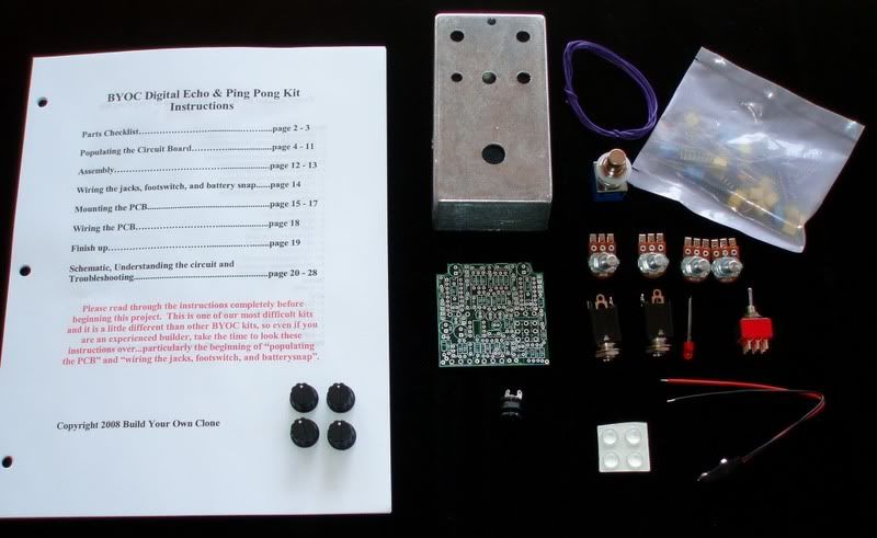
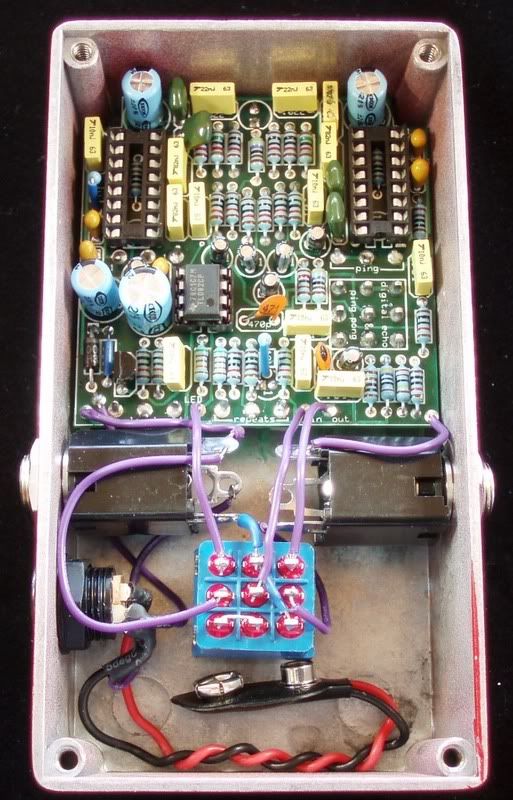
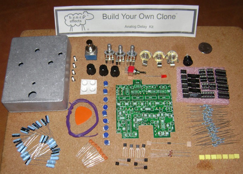
New builders to the Delay can use these pictures as a guideline when building their's for the first time. Orientations of the IC's, regulator and the electrolytic caps can be seen.
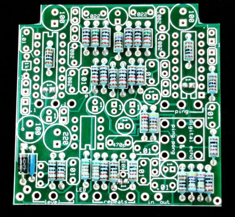
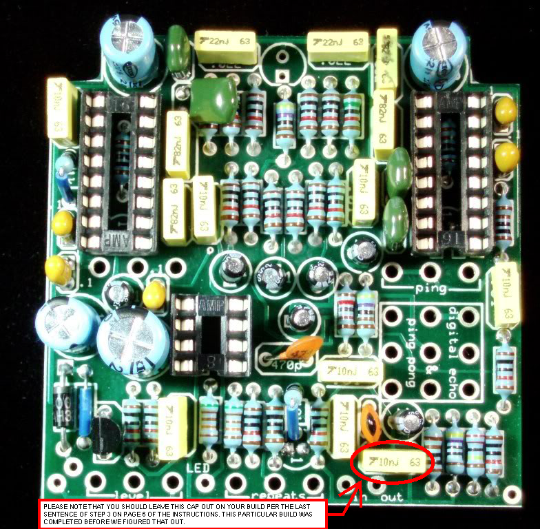
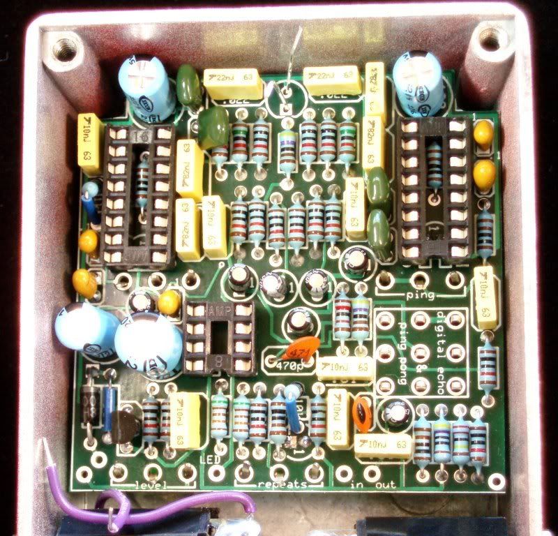
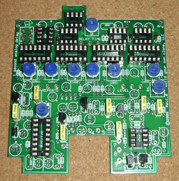
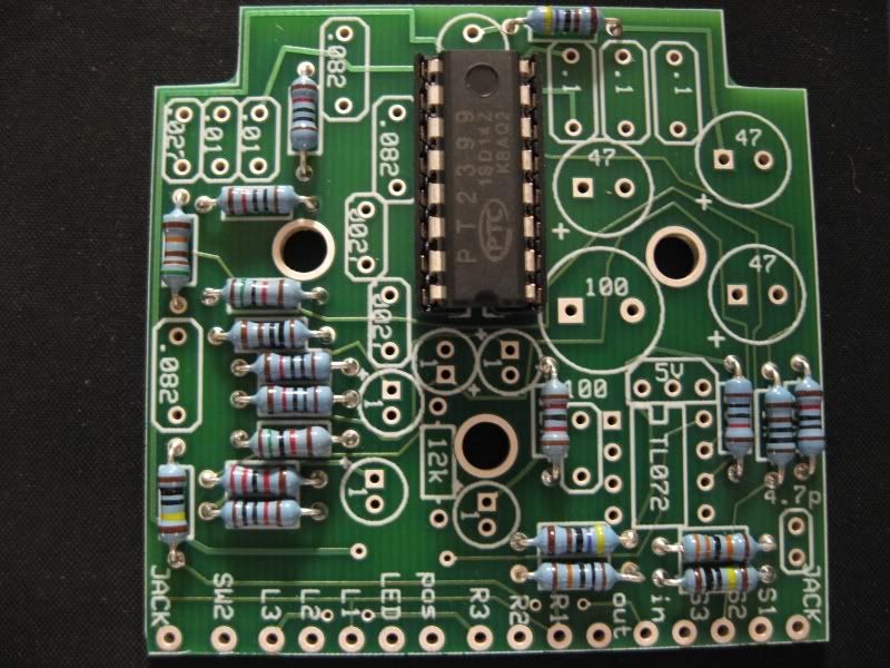
First picture is the Delay board populated with only resistors, and the PT2399 IC chip. The socket has been soldered to the board, but not the IC itself. Carefully insert the IC after socket has been soldered into place. The orientation is pointing south on this picture, as noted by the notch on the IC.
Take note that I purposely left Resistor 12k out. I later installed a switch to allow me to choose from 12k or 15k, to test out the self oscillation.
(But you need one of the 12k or 15K resistor that came with the kit in this area. Do not leave it out... unless youre experienced with the simple mod that I am referring to, which probably will end up with you needing to drill an extra hole into the enclosure for the switch)
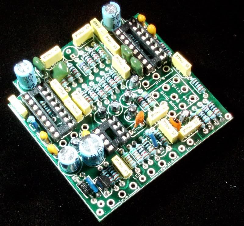
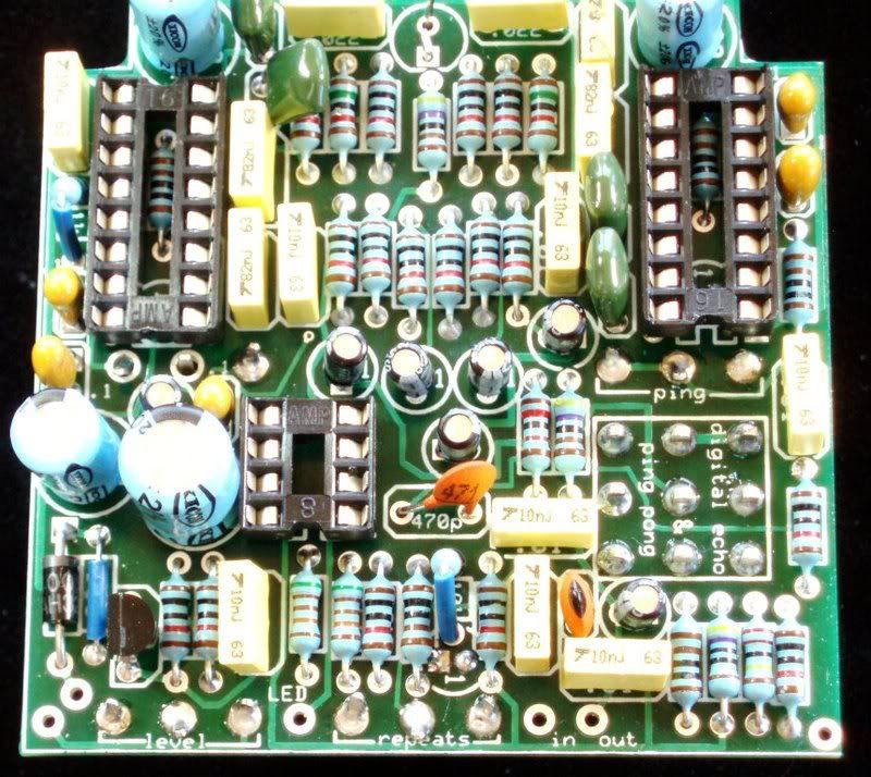
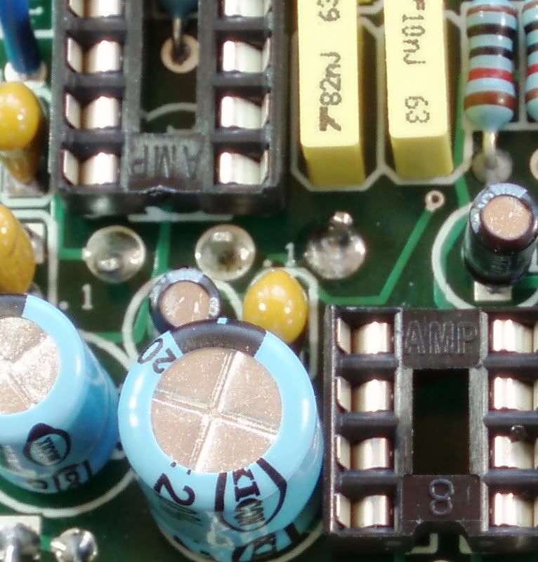
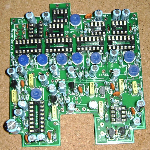
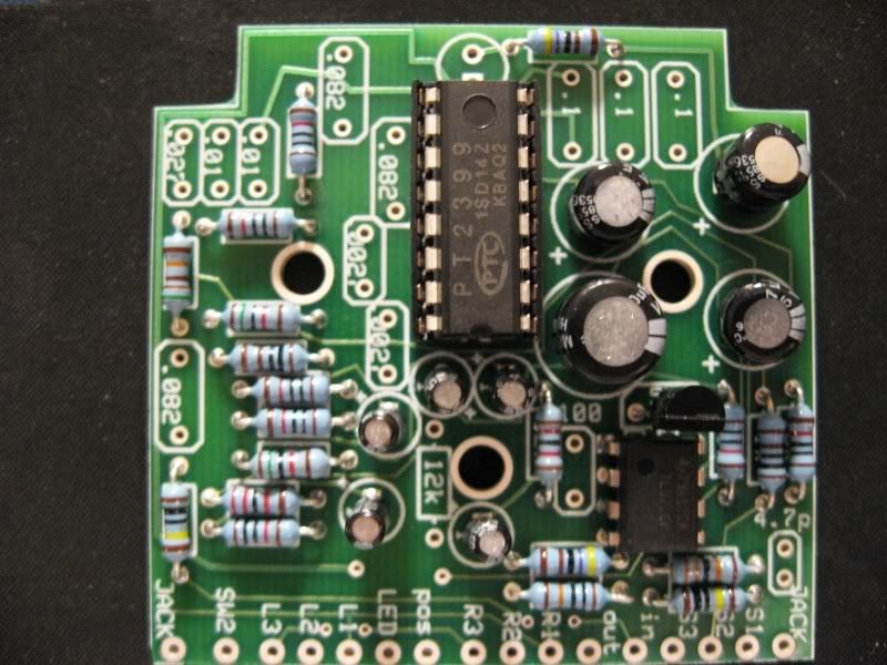
Next is another view, but included are the electrolytic capacitors, transistor and the TL072 Chip.
Notice the orientation of each. The silver strip on the caps show the negative side of the electrolytics.
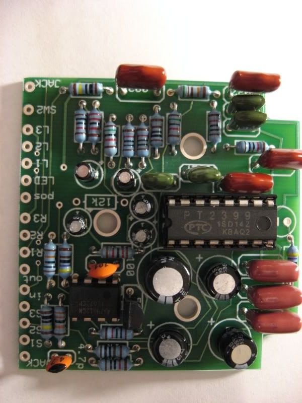
Last topside picture has the rest of the components (capacitors in this case) soldered to the board. Take note that the LED will be soldered when ready, so it is left out. Also, you can see again that the 12K resistor is still left out. I didnt want to confuse anyone with the mod shown since this is primarily based on a stock BYOC Delay.
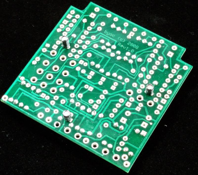
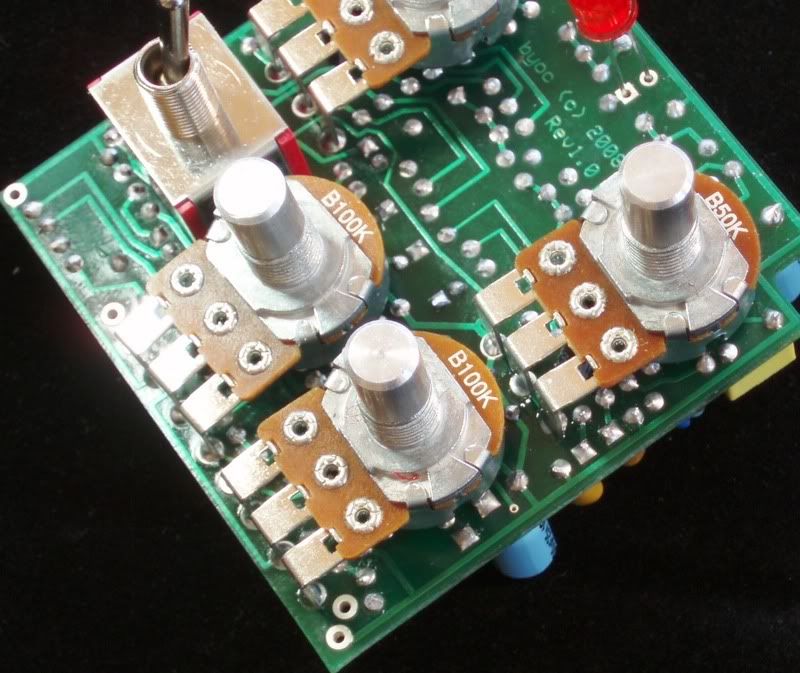
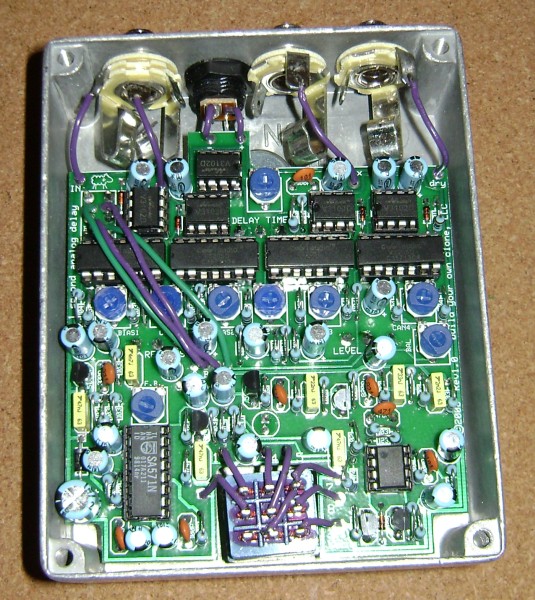
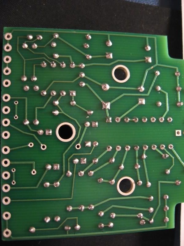
Here is an example of the soldered side of the board. Clean, although there is one solder splash that can be seen in the pic. I took the picture before cleaning the board. I then cleaned with a brush and some isopropyl alcohol.
With some patience and cleanliness, you can assemble this pedal with no worries in a small amount of time. BTW, it sounds great !!!
Enjoy!
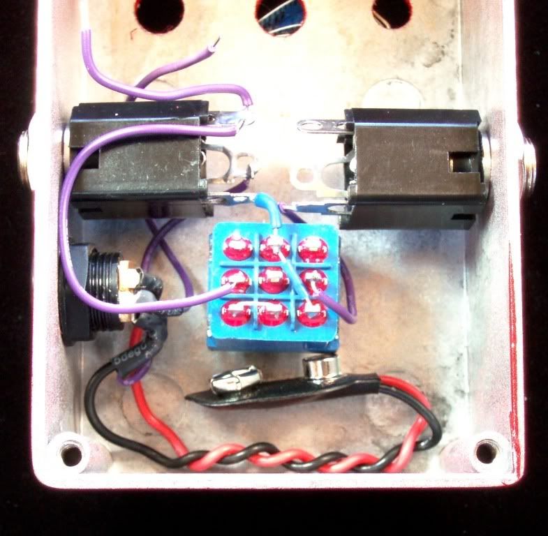
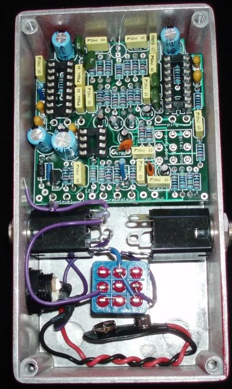
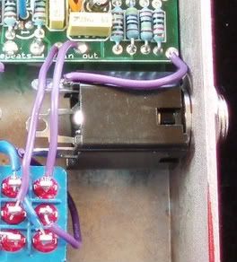
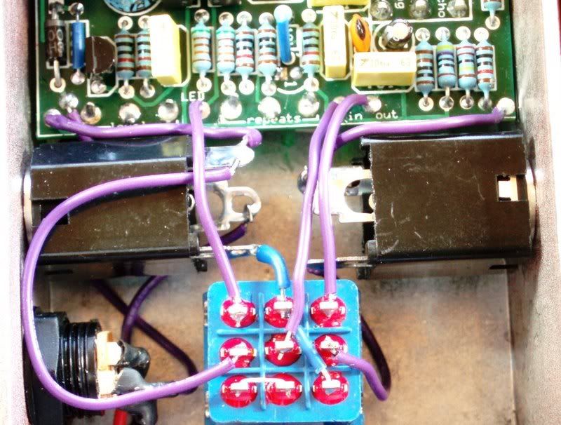
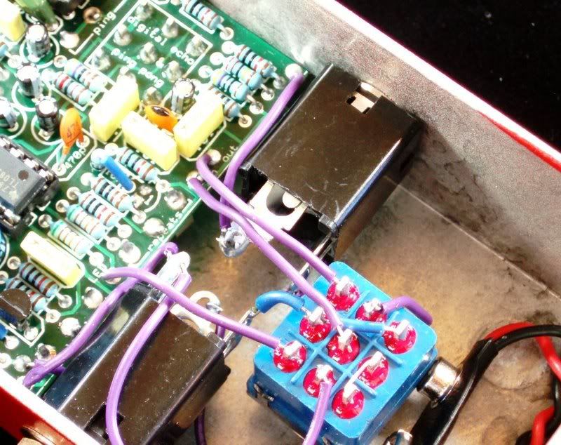
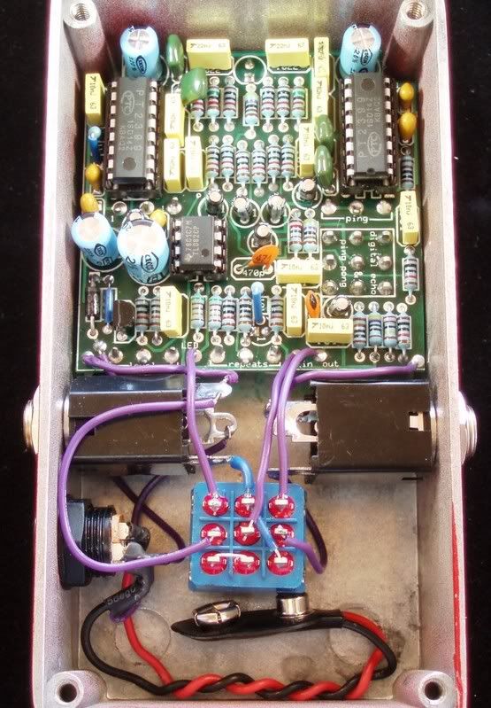
Wiring pictures soon to follow.